JEA Northside Generating Station

Last updated
JEA Northside Generating Station
JEA Northside 01.JPG
JEA Northside Generating Station from SR 105
JEA Northside Generating Station
CountryUnited States
Location Jacksonville, Florida
Coordinates 30°25′43″N81°33′10″W / 30.42861°N 81.55278°W / 30.42861; -81.55278 Coordinates: 30°25′43″N81°33′10″W / 30.42861°N 81.55278°W / 30.42861; -81.55278
StatusOperational
Commission date Unit 1 (Originally #6 fuel oil, now pet coke/coal): 1966
Unit 2 (Originally #6 fuel oil, now pet coke/coal): 1972
NSCT-3 (Gas turbine, distillate fuel oil): 1975
Unit 3 (Utility boiler, #6 fuel oil and natural gas): 1977
NSCT-4 (Gas turbine, distillate fuel oil): 1975
NSCT-5 (Gas turbine, distillate fuel oil): 1974
NSCT-6 (Gas turbine, distillate fuel oil): 1974
Owner(s) JEA
Thermal power station
Primary fuel Petroleum coke, distillate fuel oil, residual fuel oil, bituminous coal, natural gas
Turbine technologySteam, gas turbine
Cooling source St. Johns River
Power generation
Units operational7
Nameplate capacity 1,300 MWe

JEA Northside Generating Station in Jacksonville, Florida is a major power plant, one of the three power plants owned and operated by JEA, Jacksonville's municipal utilities service. It produces electricity by burning coal and petroleum coke at Units 1 and 2, formerly the largest circulating fluidized-bed combustors, (CFBs), in the world. These combustors, completed in 2002 and rated at 297.5 megawatts each, [1] [2] produce enough electricity to light more than 250,000 households. [3] In addition, Unit ST3 produces 505 megawatts of electricity by burning residual fuel oil and/or natural gas. [4]

Contents

Location

The Northside Generating Station is located north-east of the interchange of Interstate 295 and State Road 105 in the city of Jacksonville, Florida. It is 8.5 miles (13.7 km) from the Atlantic Ocean coastline, on the north bank of a back channel of the St. Johns River, which is being used as a waterway for fuel delivery as well as a source of cooling water. The Northside Generating Station also borders Timucuan Ecological and Historic Preserve that consists of North Florida wetlands and contains historic sites of Timucua peoples.

History

The Northside Generating Station began producing electricity for Jacksonville in March, 1966 with oil as its only fuel, when former Unit 1, rated at 275 megawatts, was installed. In June, 1972 a similar Unit 2 was launched, [1] but had to be shut down in 1983 due to major boiler problems. [4] A plant expansion in 1977 added a 564-megawatt Unit 3, which is still in operation today. This expansion enabled the use of oil and natural gas fuels. In 1996, JEA committed to reduce certain pollutants from the Northside Station by at least 10% when it upgraded Unit 2 (non-functional at the time) and Unit 1 by introducing the new clean coal technology. [3] This most recent upgrade was funded by JEA (234 million USD) and the U.S. Department of Energy (75 million USD). [4] Initial synchronization was achieved for Unit 2 on February 19, 2002, and for Unit 1 on May 29, 2002. [4] As a result, the facility generates significantly more power now.

CFB Technology

CFB technology is an advanced method for burning coal and other fuels efficiently while removing air emissions inside the sophisticated combustor system. CFB technology provides flexibility in utility operations because a wide variety of solid fuels can be used, including high-sulfur, high-ash coal and petroleum coke. [5]

In a CFB combustor, coal or other fuels, air, and crushed limestone or other sorbents are injected into the lower portion of the combustor for initial burning of the fuel. The combustion actually occurs in a bed of fuel, sorbent, and ash particles that are fluidized by air nozzles in the bottom of the combustor. The air expands the bed, creates turbulence for enhanced mixing, and provides most of the oxygen necessary for combustion of the fuel. As the fuel particles decrease in size through combustion and breakage, they are transported higher in the combustor where additional air is injected. As the particles continue to decrease in size, unreacted fuel, ash, and fine limestone particles are swept out of the combustor, collected in a particle separator (also called a cyclone), and recycled to the lower portion of the combustor. This is the "circulating" nature of the combustor. Drains in the bottom of the combustor remove a fraction of the bed composed primarily of ash while new fuel and sorbent are added. The combustion ash is suitable for beneficial uses such as road construction material, agricultural fertilizer, and reclaiming surface mining areas. [5]

The limestone captures up to 98% of the sulfur impurities released from the fuel. [6] When heated in the CFB combustor, the limestone, consisting primarily of calcium carbonate (CaCO3), converts to calcium oxide (CaO) and CO2 . The CaO reacts with the SO2 from the burning fuel to form calcium sulfate (CaSO4), an inert material that is removed with the combustion ash. The combustion efficiency of the CFB combustor allows the fuel to be burned at a relatively low temperature of about 1,650 °F (900 °C), thus reducing NOx formation by approximately 60% compared with conventional coal-fired technologies. [6] Greater than 99% of particulate emissions in the flue gas are removed downstream of the combustor by either an electrostatic precipitator or a fabric filter (baghouse). [5]

The heated combustor converts water in tubes lining the combustor's walls to high pressure steam. The steam is then superheated in tube bundles placed in the solids circulating stream and the flue gas stream. The superheated steam drives a steam turbine-generator to produce electricity in a conventional steam cycle.

Fuel supply

The plant uses a continuous ship unloader, the only one of its type in the continental United States. The solid fuel is transferred from barges onto the fuel conveyor system, which in turn transports it to the two largest fuel storage domes in North America. [3] Pet coke and coal travel from the ship to the domes in about twenty minutes, entirely inside a sealed system to prevent dust particles from escaping into the surrounding environment.

Water use

View of cooling towers at the Saint Johns River Power Park, located immediately north of JEA's Northside Generating Station, from SR 105. JEA Northside 02.JPG
View of cooling towers at the Saint Johns River Power Park, located immediately north of JEA's Northside Generating Station, from SR 105.

Water is delivered by an elevated intake flume from the back channel of the St. Johns River to cool the station's condensers, after which the water is returned to the back channel. This cooling water does not mix with other liquid process streams while in contact with the condensers. Because Unit 2 has been out of service since 1983, the actual demand for cooling water by Northside Generating Station at full load since that time has been approximately 620 million U.S. gallons per day (Mgd), or 430,700 US gallons (1,630 m3) per minute, to operate Units 1 and 3. Operation of the entire 3-unit plant occurred only from about 1978 until 1980. During that time, the demand for cooling water was approximately 827 Mgd (574,000 US gallons (2,170 m3) per minute): 24.5% for Unit 1, 24.5% for Unit 2, and 51% for Unit 3. This amount of surface water supplied to the station was approximately 10% of the average flow passing through the back channel of the St. Johns River. [7]

Before passing through the condensers, noncontact cooling water at Northside Generating Station is treated intermittently with a biocide to prevent biological growth on the heat exchanger tubes. Sodium hypochlorite (NaOCl) and occasionally sodium bromide (NaBr) are used. Treatment occurs no more than 2 hours per day per operating unit. The St. Johns River Power Park taps into the discharge side of the Northside Generating Station condensers to obtain cooling tower makeup. The average surface water flow supplied to the Power Park heat rejection system is 50 Mgd (34,400 US gallons (130 m3) per minute). Approximately 25% of this surface water evaporates into the atmosphere from the cooling towers. Cooling tower blowdown is routed back into Northside Generating Station's discharge collector basin. The daily average temperature of the cooling tower blowdown is limited to 96 °F (36 °C). [7]

Emissions

Preliminary Emission Tests were conducted on Units 1 and 2 over the summer of 2002. Testing was conducted on both units burning coal and petroleum coke. Results are summarized in the table below. Emissions results from both units met all emission requirements for particulate, SO2, acid gases and heavy metals. [8]

Emission Test Results for Units 1 and 2. [8]
PollutantUnitsEmission Standard Coal-fired Petroleum Coke-fired
SO2 lb/million BTU ≤ 0.150.0−0.040.03−0.13
NOx lb/million BTU≤ 0.090.04−0.060.02
Solid particulate lb/million BTU≤ 0.0110.0040.007
PM10 lb/million BTU≤ 0.0110.0060.004
SO3 lb/hour ≤ 1.10.430.0
Fluoride lb/million BTU≤ 1.57×10−41.06×10−40.95×10⁻⁴
Lead lb/million BTU≤ 2.6×10−50.56×10−50.59×10⁻⁵
Mercury lb/million BTU≤ 1.05×10−50.095×10−50.028×10⁻⁵

Conflicts and controversies

Soot coming from the JEA Northside Generating Station has prompted Distribution and Auto Services Inc. to threaten leaving Jacksonville area if the problem persists. Vehicle processing companies such as Auto Services Inc. prepare automobiles for dealers by cleaning, inspecting, customizing, and fixing defects. In 2001, such companies at Jacksonville processed 579,924 vehicles. Auto Services Inc. had to wash 50,000 cars to remove soot, the letter from the company's attorney said in 2002. The soot did not cause any damage to the vehicles, but a fallout occurring during a drizzle or when dew forms on vehicles could release acid that mars plastic equipment, the letter said. The JEA paid $82,000 to the vehicle-processing company to cover the cost of washing automobiles during the summer of 2002, according to JEA spokesman. [9]

See also

Related Research Articles

<span class="mw-page-title-main">Wood gas</span> Syngas fuel created by gasification of biomass

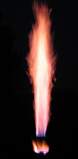
Wood gas is a fuel gas that can be used for furnaces, stoves, and vehicles. During the production process, biomass or related carbon-containing materials are gasified within the oxygen-limited environment of a wood gas generator to produce a combustible mixture. In some gasifiers this process is preceded by pyrolysis, where the biomass or coal is first converted to char, releasing methane and tar rich in polycyclic aromatic hydrocarbons.

<span class="mw-page-title-main">Power station</span> Facility generating electric power

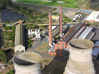
A power station, also referred to as a power plant and sometimes generating station or generating plant, is an industrial facility for the generation of electric power. Power stations are generally connected to an electrical grid.

<span class="mw-page-title-main">Incineration</span> Waste treatment process

Incineration is a waste treatment process that involves the combustion of substances contained in waste materials. Industrial plants for waste incineration are commonly referred to as waste-to-energy facilities. Incineration and other high-temperature waste treatment systems are described as "thermal treatment". Incineration of waste materials converts the waste into ash, flue gas and heat. The ash is mostly formed by the inorganic constituents of the waste and may take the form of solid lumps or particulates carried by the flue gas. The flue gases must be cleaned of gaseous and particulate pollutants before they are dispersed into the atmosphere. In some cases, the heat that is generated by incineration can be used to generate electric power.

<span class="mw-page-title-main">Gasification</span> Form of energy conversion

Gasification is a process that converts biomass- or fossil fuel-based carbonaceous materials into gases, including as the largest fractions: nitrogen (N2), carbon monoxide (CO), hydrogen (H2), and carbon dioxide (CO2). This is achieved by reacting the feedstock material at high temperatures (typically >700 °C), without combustion, via controlling the amount of oxygen and/or steam present in the reaction. The resulting gas mixture is called syngas (from synthesis gas) or producer gas and is itself a fuel due to the flammability of the H2 and CO of which the gas is largely composed. Power can be derived from the subsequent combustion of the resultant gas, and is considered to be a source of renewable energy if the gasified compounds were obtained from biomass feedstock.

<span class="mw-page-title-main">Fluidized bed combustion</span> Technology used to burn solid fuels

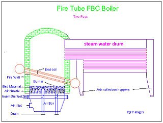
Fluidized bed combustion (FBC) is a combustion technology used to burn solid fuels.

<span class="mw-page-title-main">Fossil fuel power station</span> Facility that burns fossil fuels to produce electricity

A fossil fuel power station is a thermal power station which burns a fossil fuel, such as coal or natural gas, to produce electricity. Fossil fuel power stations have machinery to convert the heat energy of combustion into mechanical energy, which then operates an electrical generator. The prime mover may be a steam turbine, a gas turbine or, in small plants, a reciprocating gas engine. All plants use the energy extracted from the expansion of a hot gas, either steam or combustion gases. Although different energy conversion methods exist, all thermal power station conversion methods have their efficiency limited by the Carnot efficiency and therefore produce waste heat.

<span class="mw-page-title-main">Thermal power station</span> Power plant that generates electricity from heat energy

A thermal power station is a type of power station in which heat energy is converted to electrical energy. In a steam-generating cycle heat is used to boil water in a large pressure vessel to produce high-pressure steam, which drives a steam turbine connected to an electrical generator. The low-pressure exhaust from the turbine enters a steam condenser where it is cooled to produce hot condensate which is recycled to the heating process to generate more high pressure steam. This is known as a Rankine cycle.

<span class="mw-page-title-main">Cockenzie power station</span> Former coal-fired power station in Scotland

Cockenzie power station was a coal-fired power station in East Lothian, Scotland. It was situated on the south shore of the Firth of Forth, near the town of Cockenzie and Port Seton, 8 mi (13 km) east of the Scottish capital of Edinburgh. The station dominated the local coastline with its distinctive twin chimneys from 1967 until the chimneys' demolition in September 2015. Initially operated by the nationalised South of Scotland Electricity Board, it was operated by Scottish Power following the privatisation of the industry in 1991. In 2005 a WWF report named Cockenzie as the UK's least carbon-efficient power station, in terms of carbon dioxide released per unit of energy generated.

<span class="mw-page-title-main">Longannet power station</span> Former coal-fired power station in Scotland

Longannet power station was a large coal-fired power station in Fife, and the last coal-fired power station in Scotland. It was capable of co-firing biomass, natural gas and sludge. The station stood on the north bank of the Firth of Forth, near Kincardine on Forth.

<span class="mw-page-title-main">Plant Scherer</span> Coal-fired power station in Georgia, US

The Robert W. Scherer Power Plant is a coal-fired power plant in Juliette, Georgia, just north of Macon, Georgia, in the United States. The plant has four generating units, each capable of producing 930 megawatts, and is the most powerful coal-fired plant in North America. The plant is named after the former chairman and chief executive officer of Georgia Power.

<span class="mw-page-title-main">Coal-fired power station</span> Type of thermal power station

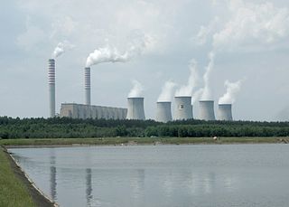
A coal-fired power station or coal power plant is a thermal power station which burns coal to generate electricity. Worldwide, there are about 8,500 coal-fired power stations totaling over 2,000 gigawatts capacity. They generate about a third of the world's electricity, but cause many illnesses and early deaths, mainly from air pollution.

<span class="mw-page-title-main">St. Clair Power Plant</span> Power generation facility

The Saint Clair Power Plant was a major coal- and oil-fired power plant owned by DTE Electric, a subsidiary of DTE Energy. It was located in St. Clair County, Michigan, on the west bank of St. Clair River. The plant was across M-29 from the newer Belle River Power Plant in East China, Michigan. The first four units of St. Clair were built in 1953–1954. Since then, three more generating units have been added to the plant. The St. Clair Power Plant generates 1982 megawatts in total. It is Detroit Edison's second largest power producer. The power plant has a large impact on the local economy, employing about 300 workers. The plant is scheduled to be closed in May 2022.

<span class="mw-page-title-main">Lynemouth power station</span> Biomass power station in Northumberland, England

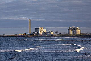
Lynemouth Power Station is a biomass power plant which provides electricity for the UK National Grid. Until March 2012, it was the main source of electricity for the nearby Alcan Lynemouth Aluminium Smelter. It is located on the coast of Northumberland, north east of the town of Ashington in north east England. The station has stood as a landmark on the Northumberland coast since it opened in 1972, and had been privately owned by aluminium company Rio Tinto Alcan throughout its operation until December 2013, when RWE npower took over. In January 2016 it was acquired by Energetický a průmyslový holding.

<span class="mw-page-title-main">Point Aconi Generating Station</span> Thermal Generating System in eastern Nova Scotia, Canada

The Point Aconi Generating Station is a 165 MW Canadian electrical generating station located in the community of Point Aconi, Nova Scotia, a rural community in the Cape Breton Regional Municipality. A thermal generating station, the Point Aconi Generating Station is owned and operated by Nova Scotia Power Corporation. It opened on August 13, 1994 following four years of construction.

<span class="mw-page-title-main">West Springfield Generating Station</span> Power plant in Massachusetts, U.S.

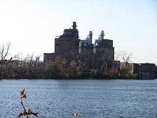
The West Springfield Generating Station, also known by its corporate name EP Energy Massachusetts, LLC, is a fossil-fuel-fired power plant located in West Springfield, Massachusetts. The station is a "peaking" facility, meaning that it primarily operates during peak electrical demand. The facility consists of two 49-megawatt (MW) combustion turbine generators fueled by natural gas or ultra low-sulphur diesel fuel, one 18 MW jet turbine that is fueled by kerosene, and one 107 MW simple-cycle steam boiler unit burning no. 6 fuel oil, ULSD or natural gas. The station also has a small auxiliary boiler for process and building heat and an emergency back-up generator. The station's management also operates several small remote power generators including two other jet turbines identical to West Springfield 10 which are the Doreen Street unit in Pittsfield, Massachusetts, and Woodland Road unit in Lee, Massachusetts as well as five run-of-river hydroelectric power stations located on the Chicopee and Deerfield Rivers.

<span class="mw-page-title-main">Tejo Power Station operations</span> Former thermoelectric power station in Lisbon, Portugal

The Tejo Power Station was a thermoelectric power station in operation from 1908 to 1975, in the Belém district of Lisbon, Portugal.

<span class="mw-page-title-main">Brayton Point Power Station</span>

Brayton Point Power Station was a coal-fired power plant located in Somerset, Massachusetts. It was the largest coal-fired generating station in New England, and was the last coal-fired power station in Massachusetts to provide power to the regional grid. It had been owned by the power company Dominion Energy New England since 2005, after it was purchased from PG&E. The plant was owned from August 2013 to April 2015 by Energy Capital Partners, and is now owned by Dynegy. The plant ceased power generation and went offline on June 1, 2017.

The circulating fluidized bed (CFB) is a type of Fluidized bed combustion that utilizes a recirculating loop for even greater efficiency of combustion. while achieving lower emission of pollutants. Reports suggest that up to 95% of pollutants can be absorbed before being emitted into the atmosphere. The technology is limited in scale however, due to its extensive use of limestone, and the fact that it produces waste byproducts.

Calcium looping (CaL), or the regenerative calcium cycle (RCC), is a second-generation carbon capture technology. It is the most developed form of carbonate looping, where a metal (M) is reversibly reacted between its carbonate form (MCO3) and its oxide form (MO) to separate carbon dioxide from other gases coming from either power generation or an industrial plant. In the calcium looping process, the two species are calcium carbonate (CaCO3) and calcium oxide (CaO). The captured carbon dioxide can then be transported to a storage site, used in enhanced oil recovery or used as a chemical feedstock. Calcium oxide is often referred to as the sorbent.

<span class="mw-page-title-main">Virginia City Hybrid Energy Center</span>

The Virginia City Hybrid Energy Center (VCHEC) is a power station located in St. Paul, in Wise County, Virginia. It is operated by Dominion Virginia Power, Dominion Resources Inc.'s electric distribution company in Virginia. The 600 MW plant began power generation in July 2012 after four years of construction. The plant deploys circulating fluidized bed boiler technology (CFB) to use a variety of fuel sources including bituminous coal, coal gob, and bio-fuels. VCHEC is placed under stringent environmental regulations by the Virginia Department of Environmental Quality (DEQ).

References

  1. 1 2 "Existing Electric Generating Units in the United States". Energy Information Administration. 2007. Retrieved 2008-06-19.
  2. "Existing Electric Generating Units in the United States, 2008" (Excel). Energy Information Administration, U.S. Department of Energy. 2008. Retrieved 2009-11-28.
  3. 1 2 3 http://www.nsrp.org/lean/lean_forum06/Tour_Description_JEA_Northside_Power_Station.pdf%5B%5D
  4. 1 2 3 4 The JEA Large-Scale CFB Combustion Demonstration Project, Clean Coal Technology, Topical Report Number 22, The U.S.Department of Energy and JEA (March, 2003)
  5. 1 2 3 "DOE/EIS-0289, Final Environmental Impact Statement for the JEA Circulating Fluidized Bed Combustor Project (June 1, 2000)" (PDF). Archived from the original (PDF) on November 19, 2004. Retrieved December 21, 2007.
  6. 1 2 Clean coal technology demonstration program project fact sheets (Report). Washington, D.C.: U.S. Department of Energy. 1996. DOE/FE-0351.
  7. 1 2 "DOE/EIS-0289, Final Environmental Impact Statement for the JEA Circulating Fluidized Bed Combustor Project (June 1, 2000)" (PDF). Archived from the original (PDF) on October 2, 2006. Retrieved December 21, 2007.
  8. 1 2 Goodrich, William; Sandell, Michael; Petti, Vincent; Rettura, Louis (2003). "Summary of air emissions from the first year operation of JEA's Northside Generating Station" (PDF). Multi-Pollutant Emission Controls and Strategies. Nashville, Tennessee: ICAC Forum. Retrieved 2006-12-20.
  9. Port tenant threatens pullout over soot 11/05/02