
Amplitude modulation (AM) is a modulation technique used in electronic communication, most commonly for transmitting messages with a radio wave. In amplitude modulation, the amplitude of the wave is varied in proportion to that of the message signal, such as an audio signal. This technique contrasts with angle modulation, in which either the frequency of the carrier wave is varied, as in frequency modulation, or its phase, as in phase modulation.

An amplifier, electronic amplifier or (informally) amp is an electronic device that can increase the magnitude of a signal. It is a two-port electronic circuit that uses electric power from a power supply to increase the amplitude of a signal applied to its input terminals, producing a proportionally greater amplitude signal at its output. The amount of amplification provided by an amplifier is measured by its gain: the ratio of output voltage, current, or power to input. An amplifier is defined as a circuit that has a power gain greater than one.

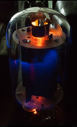
A triode is an electronic amplifying vacuum tube consisting of three electrodes inside an evacuated glass envelope: a heated filament or cathode, a grid, and a plate (anode). Developed from Lee De Forest's 1906 Audion, a partial vacuum tube that added a grid electrode to the thermionic diode, the triode was the first practical electronic amplifier and the ancestor of other types of vacuum tubes such as the tetrode and pentode. Its invention helped make amplified radio technology and long-distance telephony possible. Triodes were widely used in consumer electronics devices such as radios and televisions until the 1970s, when transistors replaced them. Today, their main remaining use is in high-power RF amplifiers in radio transmitters and industrial RF heating devices. In recent years there has been a resurgence in demand for low power triodes due to renewed interest in tube-type audio systems by audiophiles who prefer the sound of tube-based electronics.

An audio power amplifier amplifies low-power electronic audio signals, such as the signal from a radio receiver or an electric guitar pickup, to a level that is high enough for driving loudspeakers or headphones. Audio power amplifiers are found in all manner of sound systems including sound reinforcement, public address, home audio systems and musical instrument amplifiers like guitar amplifiers. It is the final electronic stage in a typical audio playback chain before the signal is sent to the loudspeakers.
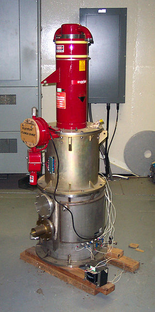
A klystron is a specialized linear-beam vacuum tube, invented in 1937 by American electrical engineers Russell and Sigurd Varian, which is used as an amplifier for high radio frequencies, from UHF up into the microwave range. Low-power klystrons are used as oscillators in terrestrial microwave relay communications links, while high-power klystrons are used as output tubes in UHF television transmitters, satellite communication, radar transmitters, and to generate the drive power for modern particle accelerators.
A valve amplifier or tube amplifier is a type of electronic amplifier that uses vacuum tubes to increase the amplitude or power of a signal. Low to medium power valve amplifiers for frequencies below the microwaves were largely replaced by solid state amplifiers in the 1960s and 1970s. Valve amplifiers can be used for applications such as guitar amplifiers, satellite transponders such as DirecTV and GPS, high quality stereo amplifiers, military applications and very high power radio and UHF television transmitters.

A traveling-wave tube or traveling-wave tube amplifier is a specialized vacuum tube that is used in electronics to amplify radio frequency (RF) signals in the microwave range. It was invented by Andrei Haeff around 1933 as a graduate student at Caltech, and its present form was invented by Rudolf Kompfner in 1942–43. The TWT belongs to a category of "linear beam" tubes, such as the klystron, in which the radio wave is amplified by absorbing power from a beam of electrons as it passes down the tube. Although there are various types of TWT, two major categories are:

A push–pull amplifier is a type of electronic circuit that uses a pair of active devices that alternately supply current to, or absorb current from, a connected load. This kind of amplifier can enhance both the load capacity and switching speed.
Predistortion is a technique used to improve the linearity of radio transmitter amplifiers.

A single-ended triode (SET) is a vacuum tube electronic amplifier that uses a single triode to produce an output, in contrast to a push-pull amplifier which uses a pair of devices with antiphase inputs to generate an output with the wanted signals added and the distortion components subtracted. Single-ended amplifiers normally operate in Class A; push-pull amplifiers can also operate in Classes AB or B without excessive net distortion, due to cancellation.
A valve audio amplifier (UK) or vacuum tube audio amplifier (US) is a valve amplifier used for sound reinforcement, sound recording and reproduction.

A reflex radio receiver, occasionally called a reflectional receiver, is a radio receiver design in which the same amplifier is used to amplify the high-frequency radio signal (RF) and low-frequency audio (sound) signal (AF). It was first invented in 1914 by German scientists Wilhelm Schloemilch and Otto von Bronk, and rediscovered and extended to multiple tubes in 1917 by Marius Latour and William H. Priess. The radio signal from the antenna and tuned circuit passes through an amplifier, is demodulated in a detector which extracts the audio signal from the radio carrier, and the resulting audio signal passes again through the same amplifier for audio amplification before being applied to the earphone or loudspeaker. The reason for using the amplifier for "double duty" was to reduce the number of active devices, vacuum tubes or transistors, required in the circuit, to reduce the cost. The economical reflex circuit was used in inexpensive vacuum tube radios in the 1920s, and was revived again in simple portable tube radios in the 1930s.
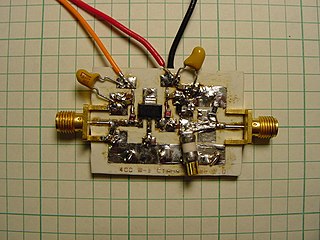
A radio-frequency power amplifier is a type of electronic amplifier that converts a low-power radio-frequency (RF) signal into a higher-power signal. Typically, RF power amplifiers are used in the final stage of a radio transmitter, their output driving the antenna. Design goals often include gain, power output, bandwidth, power efficiency, linearity, input and output impedance matching, and heat dissipation.

In electronics, biasing is the setting of DC operating conditions of an electronic component that processes time-varying signals. Many electronic devices, such as diodes, transistors and vacuum tubes, whose function is processing time-varying (AC) signals, also require a steady (DC) current or voltage at their terminals to operate correctly. This current or voltage is called bias. The AC signal applied to them is superposed on this DC bias current or voltage.
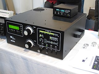
A valve RF amplifier or tube amplifier (U.S.) is a device for electrically amplifying the power of an electrical radio frequency signal.
Technical specifications and detailed information on the valve audio amplifier, including its development history.

The 833A is a vacuum tube constructed for medium power oscillator or class B or C amplifier applications. It is a medium-mu power triode with 300 watts CCS or 350 watts ICAS anode dissipation. The long grid and anode leads, plus high internal capacitance, limits this tube to 15-30 MHz maximum frequency. Being medium mu, it is normally not suitable for grounded grid operation.
The inductive output tube (IOT) or klystrode is a variety of linear-beam vacuum tube, similar to a klystron, used as a power amplifier for high frequency radio waves. It evolved in the 1980s to meet increasing efficiency requirements for high-power RF amplifiers in radio transmitters. The primary commercial use of IOTs is in UHF television transmitters, where they have mostly replaced klystrons because of their higher efficiencies and smaller size. IOTs are also used in particle accelerators. They are capable of producing power output up to about 30 kW continuous and 7 MW pulsed and gains of 20–23 dB at frequencies up to about a gigahertz.
Multidimensional Digital Pre-distortion (MDDPD), often referred to as multiband digital pre-distortion (MBDPD), is a subset of digital predistortion (DPD) that enables DPD to be applied to signals (channels) that cannot or do not pass through the same digital pre-distorter but do concurrently pass through the same nonlinear system. Its ability to do so comes from the portion of multidimensional signal theory that deals with one dimensional discrete time vector input - 1-D discrete time vector output systems as defined in Multidimensional Digital Signal Processing. The first paper in which it found application was in 1991 as seen here. None of the applications of MDDPD are able to make use of the linear shift invariant (LSI) system properties as by definition they are nonlinear and not shift-invariant although they are often approximated as shift-invariant (memoryless).
In electronics, power amplifier classes are letter symbols applied to different power amplifier types. The class gives a broad indication of an amplifier's characteristics and performance. The first three classes are related to the time period that the active amplifier device is passing current, expressed as a fraction of the period of a signal waveform applied to the input. This metric is known as conduction angle (θ). A class A amplifier is conducting through all the period of the signal (θ=360°); Class B only for one-half the input period (θ=180°), class C for much less than half the input period (θ<180°). Class D amplifiers operate their output device in a switching manner; the fraction of the time that the device is conducting may be adjusted so a pulse-width modulation output can be obtained from the stage.


