The Meillerwagen (English: Meiller vehicle) was a German World War II trailer used to transport a V-2 rocket from the 'transloading point'[1][lower-alpha 1] of the Technical Troop Area to the launching point, to erect the missile on the Brennstand (English: firing stand),[lower-alpha 2] and to act as the service gantry for fuelling and launch preparation.
The unofficial 'Meillerwagen'[lower-alpha 3] name was often used in official documents and refers to a parts supplier for the trailer, Meiller-Kipper GmbH of Munich, Germany (founded 1850). The Peenemünde Army Research Center designed the Meillerwagen, and the Gollnow & Son company assembled the Meillerwagen from supplied components. The Meillerwagen was assembled with Italian and Russianprisoner laborers of the Lager Rebstock. The Meillerwagen was vehicle code number 102 of several vehicles in a V-2 launching battery,[2] which included an 8-ton half-track launch control vehicle. Launching of V-2s from mobile equipment was studied under code nameRegenwurm ("Earthworm") to replace bunkers such as at the Watten bunker.[3]
The Meiller-Wagen (V-2 mobile wagon-erector trailer, the direct precursor to self-powered 20th/21st century transporter erector launchers)
Opel-Blitz T-Stoffwagen (fuel car-tanker, possibly of the same "Ausf. S" version as used with the Me 163B)
Kesselanhänger für Fl-Sauerstoff (liquid oxygen wagon-tanker)
Transport
After completing the process of fitting the warhead to the V-2 rocket, the Technical Troop used a 'strabo crane' at the transloading point to transfer the missile from the Vidalwagen to the Meillerwagen for transport to the launching point. Typically a Hanomag SS-100 tractor pulled the Meillerwagen up to 45km/h (28mph) forward with the rocket travelling tail-first – the maximum speed in reverse was 15km/h since the Meillerwagen's pneumatic brakes could not be coupled to the tractor when being pulled backward.
Setup
After the Meillerwagen was close to the launch point, the Firing Platoon Truck Section took charge and removed the rocket's camouflage cover and rudder protection. The control compartment batteries, alcohol-filling connection, tools, and other equipment were loaded into a box on a strut at the top of the Meillerwagen's lift frame. The Meillerwagen was moved via hand winches to the firing stand and then levelled via the two extendable outriggers with end-jacks.[1]
Lift
Meillerwagen raising a V2 rocket
The rocket was raised via the Meillerwagen lift frame and hydraulics. When vertical, the rocket was suspended above the firing stand, which was raised to touch the rocket fins. Clamping collars were used to connect the rocket to the firing stand, and the Meillerwagen was withdrawn less than a meter and the rocket was turned a quarter turn for the fuel connections to face the Meillerwagen platforms, which were lowered into position for standing. A separate three-section extendable ladder, the Magirus ladder, was used for areas of an erected rocket not accessible via the Meillerwagen.[1]
Fuelling
The hydrogen peroxide tank on the Meillerwagen (126 litres) was filled from a 2120-litre tank truck with its own pump, then the rocket was filled from the Meillerwagen tank.[1] Additional Meillerwagen piping included the following.
Fuel pipes
The elevated lifting frame was fitted with piping to fuel the rocket with A, B, P, and T-stoff.
A-Stoff: Liquid oxygen equipment consists of a pipe, which follows a circuitous route along the centreline of the lifting frame's lower half. The pipe is fixed on the lifting frame by brackets, and closed at each end by cast ramp-and-claw seals.
B-Stoff: Ethyl alcohol equipment consists of a pipe which runs along the full length of the starboard beam of the lifting frame. The pipe is slung from the underside on straps, and closed at each end by threaded seals.
P-Stoff: Compressed nitrogen (or compressed air) equipment to service the rocket consists of several batteries of compressed air tanks carried on the chassis frame, and a pipe fixed to the full length of the starboard beam of the lifting frame. The P-stoff batteries consist of one bank of six fixed tanks, and two banks of two removable tanks. (compressed air for the Meillerwagen pneumatic brakes was sourced from a separate set of two tanks across the front of the chassis frame)
T-Stoff: High test peroxide equipment consists of a pipe which runs along the starboard beam of the lifting frame from the trunnion end to the halfway point. The pipe is fitted at the upper end to the triple valve assembly, consisting of two flow valves and a three-way valve. The triple valve assembly connects to two tanks, a large measuring tank and a smaller overflow tank. The measuring tank can be filled to the rocket's required amount of T-stoff, after which any excess flows down a stand pipe to the overflow tank. The measuring tank is fitted with a ventilation stud, which vents displaced air as the tank is filled. The ventilation stud includes a ball cock fixed to a frustum stopper, which blocks the vent stud in case of accidental overfilling so that T-Stoff does not spray from the air vent. Both T-Stoff tanks are fitted with an inspection window.
Timeline
According to an official document of the time (5240/44GKdos) which describes a 110-minute launch, the Meillerwagen participates thus:
arrival at launch site and dismount rocket; duration 20 minutes from X minus 110 to minus 90 minutes.
fuelling of B-Stoff and T-Stoff; duration 20 minutes at X minus 55 minutes.
fuelling of A-Stoff and Z-Stoff; duration 10 minutes at X minus 30 minutes.
finalise rocket position, couple Meillerwagen to tractor, depart site; duration 5 minutes at X minus 13 minutes.
Structure
The structure of the Meillerwagen consisted of the wheeled trailer chassis, and the hydraulic lifting frame.
The trailer chassis was a lattice frame of tubular members. It comprised a transverse trunnion box member at the front, from which six longitudinal tube members ran aftward and converged into one large main central tube at the rear; the six longitudinal members were braced vertically and horizontally by smaller-gauge tubes. The rear central tube member supported a large horizontal-plane turntable. A steerable front truck was installed just behind the trunnion box member, while the turntable surmounted a two-axle rear bogie.
The steerable front truck was fitted with twin duplex wheels (four tyres), the inner wheels equipped with pneumatic drum brakes. The duplex wheels rode on swinging wishbone axles with transverse semi-elliptical leaf spring suspension. A steering lock was included for use during rear towing.
A turntable at the rear of the chassis frame supported a bogie, mounted on bearings so it could swivel and pivot. The bogie was fitted with two axles, a fixed middle axle and a steerable rear axle, both of the swinging wishbone type with transverse semi-elliptical leaf spring suspension. The middle axle was fitted with pneumatic brakes, while the rear axle was unbraked. A feedback steering system was included in the design, so that any change in direction by the rear bogie (and fixed middle axle) was duplicated by the steerable rear axle, but to twice the extent. The linkage for the feedback system was for used front towing, and was disengaged during rear towing.
The towing arm could be fitted to the front truck, or the steerable rear axle of the rear bogie. The towing arm was fitted with a sprung force stem, contrived so that the tow arm 'floated' horizontally at zero relative weight.
Each front corner of the chassis was fitted with a swing-out A-frame boom equipped with a screw jack and foot plate. The booms enlarged the Meillerwagen footprint to stabilise it during erection of the rocket, and provided a means of adjusting the Meillerwagen transverse level. The booms deployed outward and forward of the lifting frame trunnion axis to prevent it toppling forward or to either side.
The lifting frame was constructed of two formed I-beams, with tubular and box transverse braces. The lifting frame was fitted with plumbing for fuelling the rocket; wiring for powering and monitoring the rocket and for field telephones; accommodations for carrying and dismounting the rocket; and folding platforms to service the rocket with rungs to access them.
Electrics
The lifting frame was fitted with outlet sockets and wiring for field telephones. A main connection from the armoured launch vehicle switchboard to inlet sockets on the lifting frame provided circuits for four field phone stations at the Meillerwagen – one each at the upper and lower folding work platforms and two at the launch table.
An early configuration of the Meillerwagen included hard-wiring of two electrical power circuits and two FLAK-plug circuits for the power and control needs of the rocket. The system included four sockets at the upper and at the lower end of the lifting frame, and the connective wiring fixed along the starboard beam. The four circuits were connected to two Stotz ejecting plugs, stowed with their cables along the side of the lifting frame. All of this wiring had become redundant by the time the rocket attacks began, but was not removed from the Meillerwagen.
The Meillerwagen chassis was fitted with a Notek tail light[2] at the rear, its patch plug at the front, and the connective wiring in a conduit along the chassis frame.
Hydraulics
The lifting frame erected the rocket from horizontal to vertical, using hydraulic power. The hydraulic lifting equipment consisted of a hydraulic pump and its drive motor, a hydraulic fluid tank, a control valve group with manometers, and the lifting pistons themselves.
A 70-litre (15 gal) oil tank was fixed to the chassis frame as hydraulic fluid reservoir.
Oil under pressure flowed from the hydraulic pump to the control valve group consisting of three valves in a common housing, manipulated via one large cross-handle and two small hand taps. The large cross-handle regulated the speed of raising or lowering the lifting frame. One hand tap selected direction to either raise or lower the lifting frame. The second hand tap controlled oil flow to the lowering piston (see below), to begin lowering of the lifting frame from its vertical position.
The two hydraulic lifting pistons each consisted of one stationary cylinder and four extending telescopic cylinders. The largest extending cylinder included a flange halfway along its length, against which hydraulic pressure could be selectively applied from either above or below; it was used during raising to delay its extension until all other cylinders had extended, and also to begin the lowering process when the lifting frame was vertical (once lowering had thus been initiated, gravity finished the job).
All components of the hydraulic system were products of Meiller-Kipper GmbH, except the KdF drive engine from Volkswagen.
Platforms
Platforms
Acting as gantry, the lifting frame included a number of work platforms from which crewmen serviced the rocket. Three (later two) platforms folded flat against the lifting frame, and could be folded out from the elevated lifting frame with the use of a hand winch. Each folding platform included a safety rail of folding posts and chains.
Two side platforms or catwalks were inserted into holders for deployment on each side of the lifting frame, otherwise stowed together on brackets near the turntable. A rotating platform could be suspended from the rocket nose, to provide access to the rocket control compartments on the far side of the rocket.
The port beam of the lifting frame was fitted with around 40 rungs along its full length, with which crewmen climbed to the working platforms.
Accommodations
The lifting frame included two accommodations for the rocket, a nose clamp around the warhead and a pivoting clamp around the rocket midsection. Both accommodations included a saddle, and various mechanisms to assist dismount of the rocket onto its launch table. The mechanisms were operated with two drive shafts running up the port lifting frame beam. The drive shafts ran within the integral rungs, and were operated by a crewman with a ratchet hand tool. The two drive shafts comprised a short shaft and a long shaft; both starting at the trunnion end of the lifting frame, one running half the length of the lifting frame while the other ran the full length.
The short drive shaft operated the pivot clamp around the rocket midsection, which could move the rocket 28mm (~1") forward or backward along its centreline. The rocket midsection was fitted with a band which included trunnion pins placed in opposition; the pivot clamp held the rocket by the trunnion pins. The pivot clamp was able to rock on a transverse shaft, thus causing the rocket to move along its centreline. After erection of the rocket to a vertical position, it was held suspended above the launch table; by use of the pivot clamp, the weight of the rocket could be gently lowered onto the launch table until fully taken up, allowing the rocket to be unsecured from the lifting frame, thus dismounting it from the Meillerwagen.
The short drive shaft operated a screw sleeve, which extended to work a bell crank. The bell crank turned a transverse shaft fitted with an eccentric cam, which would push or pull the pivot clamp, thus moving the rocket forward or aftward along its centreline.
The long drive shaft ran along the full length of the port beam of the lifting frame. It entered a worm gear at the pivot clamp, then continued to the nose clamp where it entered another worm gear. A shift lever at the nose clamp disengaged the drive shaft to allow either simultaneous or independent operation of the two worm gears. The worm gear at the pivot clamp operated a pair of scissor arms, one on each side of the lifting frame to insert or extract the trunnion pins from the rocket. The worm gear at the nose clamp operated the jaws of the nose clamp to either open or close, thus enclosing or releasing the rocket.
Brakes
The Meillerwagen was equipped with pneumaticdrum brakes, installed on the front and middle axles. The middle axle brakes could also be applied mechanically with a hand-operated cable, to act as a parking brake.
The Meillerwagen's pneumatic brakes drew air pressure from the towing vehicle, and were operated by the tractor driver as an extension of his vehicle's brake circuit. A control valve handle on the Meillerwagen regulated the braking force it drew from the tractor, depending on whether the Meillerwagen was laden with a rocket or unladen.
The Meillerwagen was equipped with two compressed air reservoirs, filled from the towing vehicle. These allowed the Meillerwagen to use its pneumatic brakes when it was unhitched from the tractor. In the unhitched mode, the Meillerwagen brakes were operated from the control valve handle, to provide braking ability during winching and hand-manoeuvring around the launch site.
The brake control and regulator system were supplied by Graubremse GmbH.[citation needed] The compressed air reservoirs, pneumatic brake cylinders and drum brakes were supplied by Knorr Bremse GmbH.[2]
Accessories
The Meillerwagen carried a number of accessories on the chassis and lifting frame, both for itself and the rocket. A toolbox fixed on the chassis carried snow chains, a tyre pump, and assorted tools for the Meillerwagen and KdF motor. The chassis was equipped with a pair of blast shields, entrenching tools, a hand-steering A-frame, two jacks, a spare tyre and a folding ladder. Special trays were fixed on the chassis to carry the transport cases which held various rocket accessories such as the graphite steering vanes, the nose fuse, and the Z-Stoff (permanganate) flask.
The rocket was provided with ejecting umbilical connectors, although their precise deployment evolved. Initially these 'Stotz plugs' travelled as Meillerwagen accessories, stowed on the lifting frame along with their cables. Later, the Stotz plugs were stowed in the cable box, and a ten-metre cable mast was stowed on the lifting frame for ultimate erection on the launch table at the launch site.
Specifications
'Laden' refers to carriage of an unfuelled rocket with warhead fitted. 'Camouflage frame' is a tube-frame box assembled around the rocket and covered with tarps, rarely used during combat launches.
Total length: With towing arm – Unladen without Camouflage frame, 14700mm; Laden with Camouflage frame, 16665mm. Without towing arm – Unladen without Camouflage frame, 12610mm.
Shipping class: S (for the unladen vehicle)
Total width: Unladen without camouflage frame, 2800mm. Laden with camouflage frame, 2870mm.
Total height: Unladen without camouflage frame, 3270mm. Laden with camouflage frame, 4200mm.
Total weight: Laden, 15476kg. Unladen, 11300kg.
Axle loads: Front axle – laden, 7010kg; unladen, 5860kg. Middle and rear axle – laden, 4385kg; unladen, 2720kg.
Turning circle radius: 10700mm. Clearance: 350mm.
Maximum towing speed: forwards, 45km/h; backwards, 15km/h.
Brakes: Type – Knorr single-acting pneumatic cylinders and internal-shoe drums.
Front axle wheels: Brake cylinders, 125/140mm; drum brake shoes, 400 × 140mm; Pneumatic. Middle axle wheels: Brake cylinders, 80/110mm; drum brake shoes, 400 × 120mm; Pneumatic or cable. Pneumatic brake lines: Steel pipes, 15mm, diam × 1.5mm; rubber hose lines, 24.5mm, diam × 1.3mm. Pneumatic storage: two tanks, each of 40 litres capacity at 6kg per cm2.
Wheels: Type – split rim. Rim size: 8" × 20.
Tyres: Type – Pneumatic tyres, front axle duplex tyres, middle and rear axle single tyres. Size, 270–20. Air pressure – Front axle, 4.8 atm.; Middle and rear axle, 5.8 atm.
Wheelbase: Overall, 9800mm; trailing rear truck, 2600mm. Track width: Front axle, 1250mm (central distance between duplex tyres); middle and rear axle, 2000mm.
Hose connectors: B-material line – steel tube of 70mm ID; upper and lower connectors, M 90 × 2mm; tank drain valve, M 45 × 1.5mm. T-material line – aluminium pipe of 32mm ID; upper and lower connectors, R 13⁄4. A-material line – light alloy pipe of 70mm ID; Upper and lower connectors claw clutch size, NW 70mm. P-material line – steel tube of 10mm; 6 compressed gas bottles, 230 atm.; filling pressure with a volume of 58 L each; filling and emptying connecting pieces, AM 14 × 1,5mm.
Drive engine: Design – Stationary KdF engine (from Volkswagen) type 120/15. Working type – Four-stroke petrol Otto engine. Fuel – 74 oct gasoline; Coldstart fuel, ether. Stroke, 64mm. Bore, 75mm. Number of cylinders, 4. Capacity, 1131cm3. Compression ratio, 1:5,8. Working number of revolutions, 1470–1500 rpm. Continuous operation, 14hp. Fuel consumption under full load, ~5.4L/h. Lubricating oil consumption, about 20ml/h.
Tools for the VW Motor: 1 starting crank, coldstart fuel (ether) in canister.
An unknown number were taken east in 1945, all or none of which may still exist in the former USSR.[5]
Notes
↑ Terms in single quotation marks indicate Kennedy's terminology.
↑ A Bodenplatte (English: bottom plate) blast deflector shaped somewhat like a lemon juicer was used under the firing table.
↑ Many historical documents use the spelling 'Meilerwagen', but this has never been correct.[citation needed]
Related Research Articles
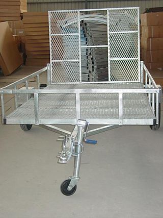
A trailer is an unpowered vehicle towed by a powered vehicle. It is commonly used for the transport of goods and materials.
A tow truck is a truck used to move disabled, improperly parked, impounded, or otherwise indisposed motor vehicles. This may involve recovering a vehicle damaged in an accident, returning one to a drivable surface in a mishap or inclement weather, or towing or transporting one via flatbed to a repair shop or other location.
Air suspension is a type of vehicle suspension powered by an electric or engine-driven air pump or compressor. This compressor pumps the air into a flexible bellows, usually made from textile-reinforced rubber. Unlike hydropneumatic suspension, which offers many similar features, air suspension does not use pressurized liquid, but pressurized air. The air pressure inflates the bellows, and raises the chassis from the axle.
A gun carriage is a frame or a mount that supports the gun barrel of an artillery piece, allowing it to be maneuvered and fired. These platforms often had wheels so that the artillery pieces could be moved more easily. Gun carriages are also used on ships to facilitate the movement and aiming of large cannons and guns. These are also used in the funeral procession of any higher authority of any state and country.
A motorcycle's suspension serves a dual purpose: contributing to the vehicle's handling and braking, and providing safety and comfort by keeping the vehicle's passengers comfortably isolated from road noise, bumps and vibrations.
The following outline is provided as an overview of and topical guide to automobiles:
The Rover 8 was a small single-cylinder 8 hp 1327 cc car made by the British Rover car company. It was Rover's first production car. It was remarkable for being supported by a backbone chassis rather than a conventional ladder frame. The first model was manufactured from 1904 to 1912. A Daimler-Knight sleeve valve engine option was available on the original model in 1911 and 1912.
The TatraT813 was a truck produced in Czechoslovakia by the Tatra company. It was produced from 1967 to 1982. The basic representative of this series was a military version of the 8×8 Kolos (Colossus), which was able to pull trailers up to a total weight of 100 tons. Tatra also produced a civilian version in either 6×6 or 4×4. After fifteen years of production, 11,751 vehicles were built in all modifications. Many units were exported to the USSR, East Germany, Romania and India.
Motorcycle components and systems for a motorcycle are engineered, manufactured, and assembled in order to produce motorcycle models with the desired performance, aesthetics, and cost. The key components of modern motorcycles are presented below.
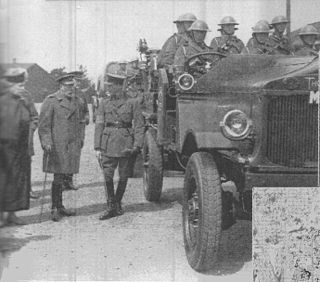
The Thornycroft Hathi was an early four wheel drive lorry built by Thornycroft in the 1920s. It was used by the British Army as an artillery tractor.
The Triumph Super 9 was a British motorcar model, first introduced by the Triumph Motor Company in 1931 at a price of £185. It continued through into 1933. It had an RAC rating of 8.9 hp.
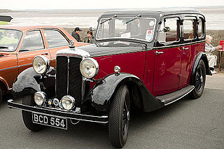
The Daimler Fifteen was a saloon car at the low end of Daimler Company’s range, offered between 1932 and 1937. It was the first Daimler product for more than two decades with an engine that breathed conventionally through poppet valves. Conventional valve gear had improved, superseding the former advantages of the Daimler-Knight sleeve-valve technology. The car's name derived from its tax rating of 15 hp. The design of its 6-cylinder 1.8-litre engine was developed from the 4-cylinder 1.2-litre Lanchester Ten which was installed in Lanchester's shorter versions of the same chassis and bodies and using the same Daimler semi-automatic transmissions.
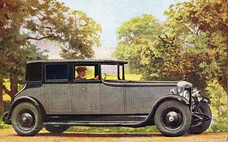
The Daimler Double-Six sleeve-valve V12 was a piston engine manufactured by The Daimler Company Limited of Coventry, England between 1926 and 1938. It was offered in four different sizes for their flagship cars.
The Lanchester Eighteen at first known as the 15/18 was announced at the beginning of October 1931. Quite unlike any previous Lanchester it was their first new car following BSA's takeover of The Lanchester Motor Company Limited in January 1931. A medium sized car was a new departure for Lanchester.
The Austin 15-20 is the smaller-engined of the almost identical pair of new cars announced by Herbert Austin in February 1906. A very complete catalogue with detailed specifications was issued at the same time. As well as the engine's smaller bore the 15-20 differed from the 25-30 by being only available with a live rear axle and not chain-drive. Otherwise the specifications were the same, the very minor differences are detailed below.
The MOWAG Shark is an armored personnel carrier produced by the MOWAG Motor Car Factory, Kreuzlingen, Switzerland.
The Audi R8 LMS Cup was a one-make sports car racing series by Audi based in Asia. Audi R8 LMS Cup cars were based on the Audi R8 LMS (GT3).
The Unimog 406 is a vehicle of the Unimog-series by Mercedes-Benz. A total of 37,069 units were manufactured by the Daimler-Benz AG in the Unimog plant in Gaggenau from 1963 to 1989. The 406 was the first medium duty Unimog, having a larger wheelbase of 2380 mm and more than twice the engine power of the Unimog 401. Unlike the initial Unimog, the 406 does not have a car engine but a heavy duty truck engine instead. Several following Unimog versions were based on the 406. There were eleven different types made of the Unimog 406, which were available in four models with a closed two-door or four-door cab, as Cabrio and as an OEM part. During its long production period, the 406 received several technical refinements. In 1964, the precombustion chamber diesel engine OM 312 was replaced with the direct injected OM 352. Disc brakes followed in 1973. For many enthusiasts, the Unimog 406 represents the classical Unimog, having agricultural and silvicultural applications. It was successful and the best embodiment of the word Universal-Motor-Gerät considering all prior Unimogs.
The SAMIL 20 is a 2-ton cargo vehicle produced in South Africa in the mid-1980s and was used as the primary light cargo carrier of the South African National Defence Force. The vehicle design is based on the German Mercedes Unimog chassis and Mark I of this vehicle was based on the Magirus Deutz 130M7FAL 4x4 truck. In Mark II, the engine was replaced with an upgraded South African built water cooled diesel engine. The vehicle is still in use with the SANDF.
References
Wikimedia Commons has media related to Meillerwagen.
1 2 3 4 5 Kennedy, Gregory P. (1983). Vengeance Weapon 2: The V-2 Guided Missile. Washington DC: Smithsonian Institution Press. pp.44, 45, 48.
1 2 3 Klee, Ernst; Merk, Otto (1965) [1963 (original German version)]. The Birth of the Missile: The Secrets of Peenemünde. Hamburg: Gerhard Stalling Verlag.
↑ Huzel, Dieter K (1960). Peenemünde to Canaveral. Englewood Cliffs NJ: Prentice Hall. p.93.
This page is based on this Wikipedia article Text is available under the CC BY-SA 4.0 license; additional terms may apply. Images, videos and audio are available under their respective licenses.