
Network topology is the arrangement of the elements of a communication network. Network topology can be used to define or describe the arrangement of various types of telecommunication networks, including command and control radio networks, industrial fieldbusses and computer networks.

In electronics and telecommunications, a crossbar switch is a collection of switches arranged in a matrix configuration. A crossbar switch has multiple input and output lines that form a crossed pattern of interconnecting lines between which a connection may be established by closing a switch located at each intersection, the elements of the matrix. Originally, a crossbar switch consisted literally of crossing metal bars that provided the input and output paths. Later implementations achieved the same switching topology in solid-state electronics. The crossbar switch is one of the principal telephone exchange architectures, together with a rotary switch, memory switch, and a crossover switch.
A nonblocking minimal spanning switch is a device that can connect N inputs to N outputs in any combination. The most familiar use of switches of this type is in a telephone exchange. The term "non-blocking" means that if it is not defective, it can always make the connection. The term "minimal" means that it has the fewest possible components, and therefore the minimal expense.
In telecommunications, a point-to-point connection refers to a communications connection between two communication endpoints or nodes. An example is a telephone call, in which one telephone is connected with one other, and what is said by one caller can only be heard by the other. This is contrasted with a point-to-multipoint or broadcast connection, in which many nodes can receive information transmitted by one node. Other examples of point-to-point communications links are leased lines and microwave radio relay.
In electronics, a banyan switch is a complex crossover switch used in electrical or optical switches.
In electronics, a crossover switch or matrix switch is a switch connecting multiple inputs to multiple outputs using complex array matrices designed to switch any one input path to any one output path(s). There are blocking and non-blocking types of cross-over switches.
A load-balanced switch is a switch architecture which guarantees 100% throughput with no central arbitration at all, at the cost of sending each packet across the crossbar twice. Load-balanced switches are a subject of research for large routers scaled past the point of practical central arbitration.
Switched fabric or switching fabric is a network topology in which network nodes interconnect via one or more network switches. Because a switched fabric network spreads network traffic across multiple physical links, it yields higher total throughput than broadcast networks, such as the early 10BASE5 version of Ethernet and most wireless networks such as Wi-Fi.

An Omega network is a network configuration often used in parallel computing architectures. It is an indirect topology that relies on the perfect shuffle interconnection algorithm.
A network on a chip or network-on-chip is a network-based communications subsystem on an integrated circuit ("microchip"), most typically between modules in a system on a chip (SoC). The modules on the IC are typically semiconductor IP cores schematizing various functions of the computer system, and are designed to be modular in the sense of network science. The network on chip is a router-based packet switching network between SoC modules.
In the field of telecommunications, a Clos network is a kind of multistage circuit-switching network which represents a theoretical idealization of practical, multistage switching systems. It was invented by Edson Erwin in 1938 and first formalized by the American engineer Charles Clos in 1952.

The SGI Origin 2000 is a family of mid-range and high-end server computers developed and manufactured by Silicon Graphics (SGI). They were introduced in 1996 to succeed the SGI Challenge and POWER Challenge. At the time of introduction, these ran the IRIX operating system, originally version 6.4 and later, 6.5. A variant of the Origin 2000 with graphics capability is known as the Onyx2. An entry-level variant based on the same architecture but with a different hardware implementation is known as the Origin 200. The Origin 2000 was succeeded by the Origin 3000 in July 2000, and was discontinued on June 30, 2002.
A time-slot interchange (TSI) switch is a network switch that stores data in RAM in one sequence, and reads it out in a different sequence. It uses RAM, a small routing memory and a counter. Like any switch, it has input and output ports. The RAM stores the packets or other data that arrive via its input terminal.
For parallel computing, the interconnection network is the heart of a parallel processing system, and many systems have failed to meet their design goals for the design of their essential components. The bandwidth limitation of the electronic interconnects prompted the need for exploring alternatives that overcome this limitation. Optics is considered as an alternative that is capable of providing inherentcommunication, parallelism, high connectivity and large bandwidth. When the communication distances exceed a few millimeters, optical interconnects provide advantage over the electronic interconnects in term of power, speed and crosstalk property. Therefore, in the construction of very powerful and large multiprocessor systems, it is advantageous to interconnect close processors physically using electronic links and far processors using optical links. Thus we use optical network like OMTSE, OTIS, and OMULT etc. The OMTSE network consists of two different systems called as optical and electrical. In this network there are using two layer of TSE network with a complete binary trees of height one and the roots of these binary trees are connected with Shuffle-Exchange fashion.
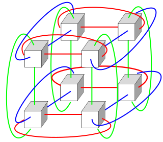
A torus interconnect is a switch-less network topology for connecting processing nodes in a parallel computer system.
In computer networking, a flit is a link-level atomic piece that forms a network packet or stream. The first flit, called the header flit holds information about this packet's route and sets up the routing behavior for all subsequent flits associated with the packet. The header flit is followed by zero or more body flits, containing the actual payload of data. The final flit, called the tail flit, performs some book keeping to close the connection between the two nodes.
A data center is a pool of resources interconnected using a communication network. A data center network (DCN) holds a pivotal role in a data center, as it interconnects all of the data center resources together. DCNs need to be scalable and efficient to connect tens or even hundreds of thousands of servers to handle the growing demands of cloud computing. Today's data centers are constrained by the interconnection network.
In computing, a logic block or configurable logic block (CLB) is a fundamental building block of field-programmable gate array (FPGA) technology. Logic blocks can be configured by the engineer to provide reconfigurable logic gates.
The STC104 switch, also known as the C104 switch in its early phases, is an asynchronous packet-routing chip that was designed for building high-performance point-to-point computer communication networks. It was developed by INMOS in the 1990s and was the first example of a general-purpose production packet routing chip. It was also the first routing chip to implement wormhole routing, to decouple packet size from the flow-control protocol, and to implement interval and two-phase randomized routing.

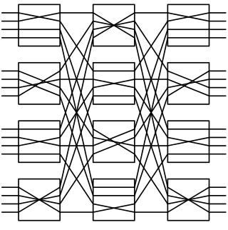
A butterfly network is a technique to link multiple computers into a high-speed network. This form of multistage interconnection network topology can be used to connect different nodes in a multiprocessor system. The interconnect network for a shared memory multiprocessor system must have low latency and high bandwidth unlike other network systems, like local area networks (LANs) or internet for three reasons: