SAE standard J1979 defines many OBD-II PIDs. All on-road vehicles and trucks sold in North America are required to support a subset of these codes, primarily for state mandated emissionsinspections. Manufacturers also define additional PIDs specific to their vehicles. Though not mandated, many motorcycles also support OBD-II PIDs.
In 1996, light duty vehicles (less than 8,500lb or 3,900kg) were the first to be mandated followed by medium duty vehicles (8,500–14,000lb or 3,900–6,400kg) in 2005.[1] They are both required to be accessed through a standardized data link connector defined by SAE J1962.
Heavy duty vehicles (greater than 14,000lb or 6,400kg) made after 2010,[1] for sale in the US are allowed to support OBD-II diagnostics through SAE standard J1939-13 (a round diagnostic connector) according to CARB in title 13 CCR 1971.1. Some heavy duty trucks in North America use the SAE J1962 OBD-II diagnostic connector that is common with passenger cars, notably Mack and Volvo Trucks, however they use 29 bit CAN identifiers (unlike 11 bit headers used by passenger cars).
Services / Modes
There are 10 diagnostic services described in the latest OBD-II standard SAE J1979. Before 2002, J1979 referred to these services as "modes". They are as follows:
Vehicle manufacturers are not required to support all services. Each manufacturer may define additional services above #9 (e.g.: service 22 as defined by SAE J2190 for Ford/GM, service 21 for Toyota) for other information e.g. the voltage of the traction battery in a hybrid electric vehicle (HEV).[2]
The nonOBD UDS services start at 0x10 to avoid overlap of ID-range.
Standard PIDs
The table below shows the standard OBD-II PIDs as defined by SAE J1979. The expected response for each PID is given, along with information on how to translate the response into meaningful data. Again, not all vehicles will support all PIDs and there can be manufacturer-defined custom PIDs that are not defined in the OBD-II standard.
Note that services 01 and 02 are basically identical, except that service 01 provides current information, whereas service 02 provides a snapshot of the same data taken at the point when the last diagnostic trouble code was set. The exceptions are PID 01, which is only available in service 01, and PID 02, which is only available in service 02. If service 02 PID 02 returns zero, then there is no snapshot and all other service 02 data is meaningless.
When using Bit-Encoded-Notation, quantities like C4 means bit 4 from data byte C. Each bit is numbered from 0 to 7, so 7 is the most significant bit and 0 is the least significant bit (See below).
NOx Sensor Corrected Concentration Sensors 3 and 4
A9
169
4
ABS Disable Switch State
[A0]= 1:Supported; 0:Unsupported
[B0]= 1:Yes;0:No
C0
192
4
PIDs supported [$C1 - $E0]
Bit encoded [A7..D0] == [PID $C1..PID $E0] See below
C3
195
2
Fuel Level Input A/B
0
25,700
%
Returns numerous data, including Drive Condition ID and Engine Speed*
C4
196
8
Exhaust Particulate Control System Diagnostic Time/Count
0
4,294,967,295
seconds / Count
B5 is Engine Idle Request B6 is Engine Stop Request* First byte = Time in seconds Second byte = Count
C5
197
4
Fuel Pressure A and B
0
5,177
kPa
C6
198
7
Byte 1 - Particulate control - driver inducement system status Byte 2,3 - Removal or block of the particulate aftertreatment system counter Byte 4,5 - Liquid regent injection system (e.g. fuel-borne catalyst) failure counter Byte 6,7 - Malfunction of Particulate control monitoring system counter
0
65,535
h
C7
199
2
Distance Since Reflash or Module Replacement
0
65,535
km
C8
200
1
NOx Control Diagnostic (NCD) and Particulate Control Diagnostic (PCD) Warning Lamp status
Service 02 accepts the same PIDs as service 01, with the same meaning,[5] but information given is from when the freeze frame[6] was created. Note that PID $02 is used to obtain the DTC that triggered the freeze frame.
A person has to send the frame number in the data section of the message.
Service 03 - Show stored Diagnostic Trouble Codes (DTCs)
17-char VIN, ASCII-encoded and left-padded with null chars (0x00) if needed to.
03
1
Calibration ID message count for PID 04. Only for ISO 9141-2, ISO 14230-4 and SAE J1850.
It will be a multiple of 4 (4 messages are needed for each ID).
04
16,32,48,64..
Calibration ID
Up to 16 ASCII chars. Data bytes not used will be reported as null bytes (0x00). Several CALID can be outputed (16 bytes each)
05
1
Calibration verification numbers (CVN) message count for PID 06. Only for ISO 9141-2, ISO 14230-4 and SAE J1850.
06
4,8,12,16
Calibration Verification Numbers (CVN) Several CVN can be output (4 bytes each) the number of CVN and CALID must match
Raw data left-padded with null characters (0x00). Usually displayed as hex string.
07
1
In-use performance tracking message count for PID 08 and 0B. Only for ISO 9141-2, ISO 14230-4 and SAE J1850.
8
10
8 if sixteen values are required to be reported, 9 if eighteen values are required to be reported, and 10 if twenty values are required to be reported (one message reports two values, each one consisting in two bytes).
08
4
In-use performance tracking for spark ignition vehicles
4 or 5 messages, each one containing 4 bytes (two values). See below
09
1
ECU name message count for PID 0A
0A
20
ECU name
ASCII-coded. Right-padded with null chars (0x00).
0B
4
In-use performance tracking for compression ignition vehicles
5 messages, each one containing 4 bytes (two values). See below
1 2 3 4 5 6 7 8 In the formula column, letters A, B, C, etc. represent the first, second, third, etc. byte of the data. For example, for two data bytes 0F 19, A = 0F and B = 19. Where a (?) appears, contradictory or incomplete information was available.
Some of the PIDs in the above table cannot be explained with a simple formula. A more elaborate explanation of these data is provided here:
Service 01 PID 00 - Show PIDs supported
A request for this PID returns 4 bytes of data (Big-endian). Each bit, from MSB to LSB, represents one of the next 32 PIDs and specifies whether that PID is supported.
For example, if the car response is BE1FA813, it can be decoded like this:
Service 01 PID 01 - Monitor status since DTCs cleared
A request for this PID returns 4 bytes of data, labeled A, B, C and D.
The first byte (A) contains two pieces of information. Bit A7 (MSB of byte A) indicates whether or not the MIL (malfunction indicator light, aka. check engine light) is illuminated. Bits A6 through A0 represent the number of diagnostic trouble codes currently flagged in the ECU.
The second, third, and fourth bytes (B, C and D) give information about the availability and completeness of certain on-board tests ("OBD readiness checks"). The third and fourth bytes are to be interpreted differently depending upon whether the engine is sparkignition (e.g. Otto or Wankel engines) or compression ignition (e.g. Diesel engines). In the second byte (B), bit 3 indicates the engine type and thus how to interpret bytes C and D, with 0 being spark (Otto or Wankel) and 1 (set) being compression (Diesel). Bits B6 to B4 and B2 to B0 are used for information about tests that not engine-type specific, and thus termed common tests. Note that for bits indicating test availability a bit set to 1 indicates available, whilst for bits indicating test completeness a bit set to 0 indicates complete.
Bits
Definition
A7
State of the CEL/MIL (on/off).
A6-A0
Number of confirmed emissions-related DTCs available for display.
B7
Reserved (should be 0)
B6-B4
Bitmap indicating completeness of common tests.
B3
Indication of engine type 0 = Spark ignition (e.g. Otto or Wankel engines) 1 = Compression ignition (e.g. Diesel engines)
B2-B0
Bitmap indicating availability of common tests.
C7-C0
Bitmap indicating availability of engine-type specific tests.
D7-D0
Bitmap indicating completeness of engine-type specific tests.
Bits from byte B representing common test indicators (those not engine-type specific) are mapped as follows:
Test availability
Test completeness
Components
B2
B6
Fuel System
B1
B5
Misfire
B0
B4
Bytes C and D are mapped as follows for spark ignition engine types (e.g. Otto or Wankel engines):
↑ A common misconception is that C4/D4 was A/C Refrigerant, however it had been listed as Reserved in J1979 for years, and was recently defined as GPF.
↑ NMHC may stand for Non-Methane HydroCarbons, but J1979 does not enlighten us. The translation would be the ammonia sensor in the SCR catalyst.
Service 01 PID 41 - Monitor status this drive cycle
A request for this PID returns 4 bytes of data. The data returned is of an identical form to that returned for PID 01, with one exception - the first byte is always zero.
Service 01 PID 78 and 79 - Exhaust Gas temperature (EGT) Bank 1 and Bank 2
A request for one of these two PIDs will return 9 bytes of data. PID 78 returns data relating to EGT sensors for bank 1, whilst PID 79 similarly returns data for bank 2. The first byte is a bit encoded field indicating which EGT sensors are supported for the respective bank.
Bytes
Description
A
EGT sensor support
B-C
Temperature read by EGT sensor 1
D-E
Temperature read by EGT sensor 2
F-G
Temperature read by EGT sensor 3
H-I
Temperature read by EGT sensor 4
The first byte is bit-encoded as follows:
Bits
Description
A7-A4
Reserved
A3
EGT sensor 4 supported?
A2
EGT sensor 3 supported?
A1
EGT sensor 2 supported?
A0
EGT sensor 1 supported?
Bytes B through I provide 16-bit integers indicating the temperatures of the sensors. The temperature values are interpreted in degrees Celsius in the range -40 to 6513.5 (scale 0.1), using the usual formula (MSB is A, LSB is B). Only values for which the corresponding sensor is supported are meaningful.
Service 03 (no PID required) - Show stored Diagnostic Trouble Codes
A request for this service returns a list of the DTCs that have been set. The list is encapsulated using the ISO 15765-2 protocol.
If there are two or fewer DTCs (up to 4 bytes) then they are returned in an ISO-TP Single Frame (SF). Three or more DTCs in the list are reported in multiple frames, with the exact count of frames dependent on the communication type and addressing details.
Each trouble code requires 2 bytes to describe. Encoded in these bytes are a category and a number. It is typically shown decoded into a five-character form like "U0158", where the first character (here 'U') represents the category the DTC belongs to, and the remaining four characters are a hexadecimal representation of the number under that category. The first two bits (A7 and A6) of the first byte (A) represent the category. The remaining 14 bits represent the number. Of note is that since the second character is formed from only two bits, it can thus only be within the range 0-3.
Bits
Definition
A7-A6
Category 00: P - Powertrain 01: C - Chassis 10: B - Body 11: U - Network[lower-alpha 1]
A5-B0
Number (within category)
↑ Whilst this is commonly referred to as the network category, it may originally have been the 'undefined' category, hence the use of the letter 'U' rather than 'N'.
An example DTC of "U0158" would be decoded as follows:
Bit
A7
A6
A5
A4
A3
A2
A1
A0
B7
B6
B5
B4
B3
B2
B1
B0
Binary
1
1
0
0
0
0
0
1
0
1
0
1
1
0
0
0
Hexadecimal
C
1
5
8
Decoded DTC
U
0
1
5
8
The resulting five-character code, e.g. "U0158", can be looked up in a table of OBD-II DTCs to get an actual description of what it represents. Of note, whilst some blocks of DTC code ranges have generic meanings that apply to all vehicles and manufacturers, the meanings of others can vary per manufacturer or even model.
It is also worth noting that DTCs may sometimes be encountered in a four-character form, e.g. "C158", which is simply the plain hexadecimal representation of the two bytes, with proper decoding with respect to the category not having been performed.
Service 09 PID 08 - In-use performance tracking for spark ignition engines
It provides information about track in-use performance for catalyst banks, oxygen sensor banks, evaporative leak detection systems, EGR systems and secondary air system.
The numerator for each component or system tracks the number of times that all conditions necessary for a specific monitor to detect a malfunction have been encountered. The denominator for each component or system tracks the number of times that the vehicle has been operated in the specified conditions.
The count of data items should be reported at the beginning (the first byte).
All data items of the In-use Performance Tracking record consist of two bytes and are reported in this order (each message contains two items, hence the message length is 4).
Mnemonic
Description
OBDCOND
OBD Monitoring Conditions Encountered Counts
IGNCNTR
Ignition Counter
CATCOMP1
Catalyst Monitor Completion Counts Bank 1
CATCOND1
Catalyst Monitor Conditions Encountered Counts Bank 1
CATCOMP2
Catalyst Monitor Completion Counts Bank 2
CATCOND2
Catalyst Monitor Conditions Encountered Counts Bank 2
O2SCOMP1
O2 Sensor Monitor Completion Counts Bank 1
O2SCOND1
O2 Sensor Monitor Conditions Encountered Counts Bank 1
O2SCOMP2
O2 Sensor Monitor Completion Counts Bank 2
O2SCOND2
O2 Sensor Monitor Conditions Encountered Counts Bank 2
EGRCOMP
EGR Monitor Completion Condition Counts
EGRCOND
EGR Monitor Conditions Encountered Counts
AIRCOMP
AIR Monitor Completion Condition Counts (Secondary Air)
AIRCOND
AIR Monitor Conditions Encountered Counts (Secondary Air)
EVAPCOMP
EVAP Monitor Completion Condition Counts
EVAPCOND
EVAP Monitor Conditions Encountered Counts
SO2SCOMP1
Secondary O2 Sensor Monitor Completion Counts Bank 1
SO2SCOND1
Secondary O2 Sensor Monitor Conditions Encountered Counts Bank 1
SO2SCOMP2
Secondary O2 Sensor Monitor Completion Counts Bank 2
SO2SCOND2
Secondary O2 Sensor Monitor Conditions Encountered Counts Bank 2
Service 09 PID 0B - In-use performance tracking for compression ignition engines
It provides information about track in-use performance for NMHC catalyst, NOx catalyst monitor, NOx adsorber monitor, PM filter monitor, exhaust gas sensor monitor, EGR/ VVT monitor, boost pressure monitor and fuel system monitor.
All data items consist of two bytes and are reported in this order (each message contains two items, hence message length is 4):
Some PIDs are to be interpreted specially, and aren't necessarily exactly bitwise encoded, or in any scale. The values for these PIDs are enumerated.
Service 01 PID 03 - Fuel system status
A request for this PID returns 2 bytes of data. The first byte describes fuel system #1. The second byte describes fuel system #2 (if it exists) and is encoded identically to the first byte. The meaning assigned to the value of each byte is as follows:
Value
Description
0
The motor is off
1
Open loop due to insufficient engine temperature
2
Closed loop, using oxygen sensor feedback to determine fuel mix
4
Open loop due to engine load OR fuel cut due to deceleration
8
Open loop due to system failure
16
Closed loop, using at least one oxygen sensor but there is a fault in the feedback system
Any other value is an invalid response.
Service 01 PID 12 - Commanded secondary air status
A request for this PID returns a single byte of data which describes the secondary air status.
Value
Description
1
Upstream
2
Downstream of catalytic converter
4
From the outside atmosphere or off
8
Pump commanded on for diagnostics
Any other value is an invalid response.
Service 01 PID 1C - OBD standards this vehicle conforms to
A request for this PID returns a single byte of data which describes which OBD standards this ECU was designed to comply with. The different values the data byte can hold are shown below, next to what they mean:
Heavy Duty On-Board Diagnostics (Child/Partial) (HD OBD-C)
20
Heavy Duty On-Board Diagnostics (HD OBD)
21
World Wide Harmonized OBD (WWH OBD)
22
Reserved
23
Heavy Duty Euro OBD Stage I without NOx control (HD EOBD-I)
24
Heavy Duty Euro OBD Stage I with NOx control (HD EOBD-I N)
25
Heavy Duty Euro OBD Stage II without NOx control (HD EOBD-II)
26
Heavy Duty Euro OBD Stage II with NOx control (HD EOBD-II N)
27
Reserved
28
Brazil OBD Phase 1 (OBDBr-1)
29
Brazil OBD Phase 2 (OBDBr-2)
30
Korean OBD (KOBD)
31
India OBD I (IOBD I)
32
India OBD II (IOBD II)
33
Heavy Duty Euro OBD Stage VI (HD EOBD-IV)
34-250
Reserved
251-255
Not available for assignment (SAE J1939 special meaning)
Service 01 PID 51 - Fuel Type Coding
This PID returns a value from an enumerated list giving the fuel type of the vehicle. The fuel type is returned as a single byte, and the value is given by the following table:
Any other value is reserved by ISO/SAE. There are currently no definitions for flexible-fuel vehicle.
Non-standard PIDs
The majority of all OBD-II PIDs in use are non-standard. For most modern vehicles, there are many more functions supported on the OBD-II interface than are covered by the standard PIDs, and there is relatively minor overlap between vehicle manufacturers for these non-standard PIDs.
There is very limited information available in the public domain for non-standard PIDs. The primary source of information on non-standard PIDs across different manufacturers is maintained by the US-based Equipment and Tool Institute and only available to members. The price of ETI membership for access to scan codes varies based on company size defined by annual sales of automotive tools and equipment in North America:
Annual Sales in North America
Annual Dues
Under $10,000,000
$5,000
$10,000,000 - $50,000,000
$7,500
Greater than $50,000,000
$10,000
However, even ETI membership will not provide full documentation for non-standard PIDs. ETI states:[7][8]
Some OEMs refuse to use ETI as a one-stop source of scan tool information. They prefer to do business with each tool company separately. These companies also require that you enter into a contract with them. The charges vary but here is a snapshot as of April 13th, 2015 of the per year charges:
GM
$50,000
Honda
$5,000
Suzuki
$1,000
BMW
$25,500 plus $2,000 per update. Updates occur annually.
CAN (11-bit) bus format
As defined in ISO 15765-4, emissions protocols (including OBD-II, EOBD, UDS, etc.) use the ISO-TP transport layer (ISO 15765-2). All CAN frames sent using ISO-TP use a data length of 8 bytes (and DLC of 8). It is recommended to pad the unused data bytes with 0xCC.
The PID query and response occurs on the vehicle's CAN bus. Standard OBD requests and responses use functional addresses. The diagnostic reader initiates a query using CAN ID 7DFh, which acts as a broadcast address, and accepts responses from any ID in the range 7E8h to 7EFh. ECUs that can respond to OBD queries listen both to the functional broadcast ID of 7DFh and one assigned ID in the range 7E0h to 7E7h. Their response has an ID of their assigned ID plus 8 e.g. 7E8h through 7EFh.
This approach allows up to eight ECUs, each independently responding to OBD queries. The diagnostic reader can use the ID in the ECU response frame to continue communication with a specific ECU. In particular, multi-frame communication requires a response to the specific ECU ID rather than to ID 7DFh.
CAN bus may also be used for communication beyond the standard OBD messages. Physical addressing uses particular CAN IDs for specific modules (e.g., 720h for the instrument cluster in Fords) with proprietary frame payloads.
Query
The functional PID query is sent to the vehicle on the CAN bus at ID 7DFh, using 8 data bytes. The bytes are:
Byte
PID Type
0
1
2
3
4
5
6
7
SAE Standard
Number of additional data bytes: 2
Service 01 = show current data; 02 = freeze frame; etc.
The vehicle responds to the PID query on the CAN bus with message IDs that depend on which module responded. Typically the engine or main ECU responds at ID 7E8h. Other modules, like the hybrid controller or battery controller in a Prius, respond at 07E9h, 07EAh, 07EBh, etc. These are 8h higher than the physical address the module responds to. Even though the number of bytes in the returned value is variable, the message uses 8 data bytes regardless (CAN bus protocol form Frameformat with 8 data bytes). The bytes are:
Byte
CAN Address
0
1
2
3
4
5
6
7
SAE Standard 7E8h, 7E9h, 7EAh, etc.
Number of additional data bytes: 3 to 6
Custom service Same as query, except that 40h is added to the service value. So: 41h = show current data; 42h = freeze frame; etc.
PID code (e.g.: 05 = Engine coolant temperature)
value of the specified parameter, byte 0
value, byte 1 (optional)
value, byte 2 (optional)
value, byte 3 (optional)
not used (may be 00h or 55h)
Vehicle specific 7E8h, or 8h + physical ID of module.
Number of additional data bytes: 4to 7
Custom service: same as query, except that 40h is added to the service value.(e.g.: 62h = response to service 22h request)
PID code (e.g.: 4980h)
value of the specified parameter, byte 0
value, byte 1 (optional)
value, byte 2 (optional)
value, byte 3 (optional)
Vehicle specific 7E8h, or 8h + physical ID of module.
Number of additional data bytes: 3
7Fh this a general response usually indicating the module doesn't recognize the request.
Custom service: (e.g.: 22h = enhanced diagnostic data by PID, 21h = enhanced data by offset)
A controller area network is a vehicle bus standard designed to allow microcontrollers and devices to communicate with each other. It is a message-based protocol, designed originally for multiplex electrical wiring within automobiles to save on copper, but it can also be used in many other contexts. For each device, the data in a frame is transmitted serially but in such a way that if more than one device transmits at the same time, the highest priority device can continue while the others back off. Frames are received by all devices, including by the transmitting device.
Modbus or MODBUS is a client/server data communications protocol in the application layer. It was originally published by Modicon in 1979 for use with its programmable logic controllers (PLCs). Modbus has become a de facto standard communication protocol for communication between industrial electronic devices in a wide range of buses and network.
A vehicle bus is a specialized internal communications network that interconnects components inside a vehicle. In electronics, a bus is simply a device that connects multiple electrical or electronic devices together. Special requirements for vehicle control such as assurance of message delivery, of non-conflicting messages, of minimum time of delivery, of low cost, and of EMF noise resilience, as well as redundant routing and other characteristics mandate the use of less common networking protocols. Protocols include Controller Area Network (CAN), Local Interconnect Network (LIN) and others. Conventional computer networking technologies are rarely used, except in aircraft, where implementations of the ARINC 664 such as the Avionics Full-Duplex Switched Ethernet are used. Aircraft that use AFDX include the B787, the A400M and the A380. Trains commonly use Ethernet Consist Network (ECN). All cars sold in the United States since 1996 are required to have an On-Board Diagnostics connector, for access to the car's electronic controllers.
Society of Automotive Engineers standard SAE J1939 is the vehicle bus recommended practice used for communication and diagnostics among vehicle components. Originating in the car and heavy-duty truck industry in the United States, it is now widely used in other parts of the world.
LIN is a network protocol used for communication between components in modern vehicles. It is a low-cost single-wire serial protocol that supports communications up to 19.2 Kbit/s with a maximum bus length of 40 metres (131.2 ft).
A data logger is an electronic device that records data over time or about location either with a built-in instrument or sensor or via external instruments and sensors. Increasingly, but not entirely, they are based on a digital processor, and called digital data loggers (DDL). They generally are small, battery-powered, portable, and equipped with a microprocessor, internal memory for data storage, and sensors. Some data loggers interface with a personal computer and use software to activate the data logger and view and analyze the collected data, while others have a local interface device and can be used as a stand-alone device.
On-board diagnostics (OBD) is a term referring to a vehicle's self-diagnostic and reporting capability. In the United States, this self-diagnostic is a requirement to comply with Federal Emissions standards to detect failures that may increase the vehicle tailpipe emissions to more than 150% of the standard to which it was originally certified.
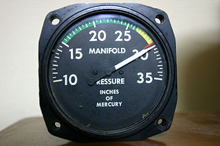
The manifold absolute pressure sensor is one of the sensors used in an internal combustion engine's electronic control system.
Chip tuning is changing or modifying an erasable programmable read only memory chip in an automobile's or other vehicles electronic control unit to achieve superior performance, whether it be more power, cleaner emissions, or better fuel efficiency. Engine manufacturers generally use a conservative electronic control unit map to allow for individual engine variations, as well as infrequent servicing and poor-quality fuel. Vehicles with a remapped electronic control unit may be more sensitive to fuel quality and service schedules.
Motronic is the trade name given to a range of digital engine control units developed by Robert Bosch GmbH which combined control of fuel injection and ignition in a single unit. By controlling both major systems in a single unit, many aspects of the engine's characteristics can be improved.
Renix was a joint venture by Renault and Bendix that designed and manufactured automobile electronic ignitions, fuel injection systems, electronic automatic transmission controls, and various engine sensors. Major applications included various Renault and Volvo vehicles. The name became synonymous in the U.S. with the computer and fuel injection system used on the AMC/Jeep 2.5 L I4 and 4.0 L I6 engines.
Digifant is an Engine Management System operated by an Engine Control Unit that actuates outputs, such as fuel injection and ignition systems, using information derived from sensor inputs, such as engine speed, exhaust oxygen and intake air flow. Digifant was designed by Volkswagen Group, in cooperation with Robert Bosch GmbH.
Society of Automotive Engineers standard SAE J1708 is a standard used for serial communications between ECUs on a heavy duty vehicle and also between a computer and the vehicle. With respect to Open System Interconnection model (OSI), J1708 defines the physical layer. Common higher layer protocols that operate on top of J1708 are SAE J1587 and SAE J1922. The protocol is maintained by SAE International.
OBDuino is an open source trip computer design based on the Arduino platform. An OBDuino may be assembled and customised by an electronics hobbyist; it displays information such as instantaneous fuel economy, engine tuning parameters etc. on an LCD.
ISO 15765-2, or ISO-TP (Transport Layer), is an international standard for sending data packets over a CAN-Bus. The protocol allows for the transport of messages that exceed the eight byte maximum payload of CAN frames. ISO-TP segments longer messages into multiple frames, adding metadata (CAN-TP Header) that allows the interpretation of individual frames and reassembly into a complete message packet by the recipient. It can carry up to 232-1 (4294967295) bytes of payload per message packet starting from the 2016 version. Prior version were limited to a maximum payload size of 4095 bytes.
The Lucas 14CUX is an automotive electronic fuel injection system developed by Lucas Industries and fitted to the Rover V8 engine in Land Rover vehicles between 1990 and 1995. The system was also paired with the Rover V8 by a number of low-volume manufacturers such as TVR, Marcos, Ginetta, and Morgan.
An automotive scan tool (scanner) is an electronic tool used to interface with, diagnose and, sometimes, reprogram vehicle control modules.
The ELM327 is a programmed microcontroller produced for translating the on-board diagnostics (OBD) interface found in most modern cars. The ELM327 command protocol is one of the most popular PC-to-OBD interface standards and is also implemented by other vendors.
Unified Diagnostic Services (UDS) is a diagnostic communication protocol used in electronic control units (ECUs) within automotive electronics, which is specified in the ISO 14229-1. It is derived from ISO 14230-3 (KWP2000) and the now obsolete ISO 15765-3. 'Unified' in this context means that it is an international and not a company-specific standard. By now this communication protocol is used in all new ECUs made by Tier 1 suppliers of Original Equipment Manufacturer (OEM), and is incorporated into other standards, such as AUTOSAR. The ECUs in modern vehicles control nearly all functions, including electronic fuel injection (EFI), engine control, the transmission, anti-lock braking system, door locks, braking, window operation, and more.
CAN FD is a data-communication protocol used for broadcasting sensor data and control information on 2 wire interconnections between different parts of electronic instrumentation and control system. This protocol is used in modern high performance vehicles.
"E/E Diagnostic Test Modes". Vehicle E E System Diagnostic Standards Committee. SAE J1979. SAE International. 2017-02-16. doi:10.4271/J1979_201702.
"Digital Annex of E/E Diagnostic Test Modes". Vehicle E E System Diagnostic Standards Committee. SAE J1979-Da. SAE International. 2017-02-16. doi:10.4271/J1979DA_201702.
This page is based on this Wikipedia article Text is available under the CC BY-SA 4.0 license; additional terms may apply. Images, videos and audio are available under their respective licenses.