Overview
OR-AND-invert gates implement the inverted product of sums. groups of , input signals combined with OR, and the results then combined with NAND.
OR-AND-invert gates or OAI-gates are logic gates comprising OR gates followed by a NAND gate. They can be efficiently implemented in logic families like CMOS and TTL. They are dual to AND-OR-invert gates.
OR-AND-invert gates implement the inverted product of sums. groups of , input signals combined with OR, and the results then combined with NAND.

A 2-1-OAI gate realizes the function
with the truth table shown below.
| Truth table 2-1 OAI | |||
| Input A B C | Output Y | ||
| 0 | 0 | 0 | 1 |
| 0 | 0 | 1 | 1 |
| 0 | 1 | 0 | 1 |
| 0 | 1 | 1 | 0 |
| 1 | 0 | 0 | 1 |
| 1 | 0 | 1 | 0 |
| 1 | 1 | 0 | 1 |
| 1 | 1 | 1 | 0 |
A 2-2-OAI gate realizes the function
with the truth table shown below.
| Truth table 2-2 OAI | ||||
| INPUT A B C D | OUTPUT Q | |||
| 0 | 0 | 0 | 0 | 1 |
| 0 | 0 | 0 | 1 | 1 |
| 0 | 0 | 1 | 0 | 1 |
| 0 | 0 | 1 | 1 | 1 |
| 0 | 1 | 0 | 0 | 1 |
| 0 | 1 | 0 | 1 | 0 |
| 0 | 1 | 1 | 0 | 0 |
| 0 | 1 | 1 | 1 | 0 |
| 1 | 0 | 0 | 0 | 1 |
| 1 | 0 | 0 | 1 | 0 |
| 1 | 0 | 1 | 0 | 0 |
| 1 | 0 | 1 | 1 | 0 |
| 1 | 1 | 0 | 0 | 1 |
| 1 | 1 | 0 | 1 | 0 |
| 1 | 1 | 1 | 0 | 0 |
| 1 | 1 | 1 | 1 | 0 |

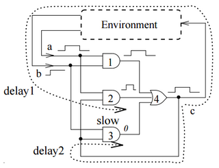
OAI-gates can efficiently be implemented as complex gates. An example of a 3-1 OAI-gate is shown in the figure below. [1]
One possibility of implementing an XOR gate is by using a 2-2-OAI-gate with non-inverted and inverted inputs. [2]


A logic gate is a device that performs a Boolean function, a logical operation performed on one or more binary inputs that produces a single binary output. Depending on the context, the term may refer to an ideal logic gate, one that has, for instance, zero rise time and unlimited fan-out, or it may refer to a non-ideal physical device.

In Boolean functions and propositional calculus, the Sheffer stroke denotes a logical operation that is equivalent to the negation of the conjunction operation, expressed in ordinary language as "not both". It is also called non-conjunction, or alternative denial since it says in effect that at least one of its operands is false, or NAND. In digital electronics, it corresponds to the NAND gate. It is named after Henry Maurice Sheffer and written as or as or as or as in Polish notation by Łukasiewicz.

In electronics, a multiplexer, also known as a data selector, is a device that selects between several analog or digital input signals and forwards the selected input to a single output line. The selection is directed by a separate set of digital inputs known as select lines. A multiplexer of inputs has select lines, which are used to select which input line to send to the output.

In digital logic, an inverter or NOT gate is a logic gate which implements logical negation. It outputs a bit opposite of the bit that is put into it. The bits are typically implemented as two differing voltage levels.

Exclusive or, exclusive disjunction, exclusive alternation, logical non-equivalence, or logical inequality is a logical operator whose negation is the logical biconditional. With two inputs, XOR is true if and only if the inputs differ. With multiple inputs, XOR is true if and only if the number of true inputs is odd.
An adder, or summer, is a digital circuit that performs addition of numbers. In many computers and other kinds of processors, adders are used in the arithmetic logic units (ALUs). They are also used in other parts of the processor, where they are used to calculate addresses, table indices, increment and decrement operators and similar operations.
In logic, a truth function is a function that accepts truth values as input and produces a unique truth value as output. In other words: the input and output of a truth function are all truth values; a truth function will always output exactly one truth value, and inputting the same truth value(s) will always output the same truth value. The typical example is in propositional logic, wherein a compound statement is constructed using individual statements connected by logical connectives; if the truth value of the compound statement is entirely determined by the truth value(s) of the constituent statement(s), the compound statement is called a truth function, and any logical connectives used are said to be truth functional.
The AND gate is a basic digital logic gate that implements logical conjunction (∧) from mathematical logic – AND gate behaves according to the truth table. A HIGH output (1) results only if all the inputs to the AND gate are HIGH (1). If not all inputs to the AND gate are HIGH, LOW output results. The function can be extended to any number of inputs.
The OR gate is a digital logic gate that implements logical disjunction. The OR gate outputs "true" if any of its inputs are "true"; otherwise it outputs "false". The input and output states are normally represented by different voltage levels.
In digital computing, the Muller C-element is a small binary logic circuit widely used in design of asynchronous circuits and systems. It outputs 0 when all inputs are 0, it outputs 1 when all inputs are 1, and it retains its output state otherwise. It was specified formally in 1955 by David E. Muller and first used in ILLIAC II computer. In terms of the theory of lattices, the C-element is a semimodular distributive circuit, whose operation in time is described by a Hasse diagram. The C-element is closely related to the rendezvous and join elements, where an input is not allowed to change twice in succession. In some cases, when relations between delays are known, the C-element can be realized as a sum-of-product (SOP) circuit. Earlier techniques for implementing the C-element include Schmitt trigger, Eccles-Jordan flip-flop and last moving point flip-flop.
In digital electronics, a NAND gate (NOT-AND) is a logic gate which produces an output which is false only if all its inputs are true; thus its output is complement to that of an AND gate. A LOW (0) output results only if all the inputs to the gate are HIGH (1); if any input is LOW (0), a HIGH (1) output results. A NAND gate is made using transistors and junction diodes. By De Morgan's laws, a two-input NAND gate's logic may be expressed as , making a NAND gate equivalent to inverters followed by an OR gate.
XOR gate is a digital logic gate that gives a true output when the number of true inputs is odd. An XOR gate implements an exclusive or from mathematical logic; that is, a true output results if one, and only one, of the inputs to the gate is true. If both inputs are false (0/LOW) or both are true, a false output results. XOR represents the inequality function, i.e., the output is true if the inputs are not alike otherwise the output is false. A way to remember XOR is "must have one or the other but not both".
The NAND Boolean function has the property of functional completeness. This means that any Boolean expression can be re-expressed by an equivalent expression utilizing only NAND operations. For example, the function NOT(x) may be equivalently expressed as NAND(x,x). In the field of digital electronic circuits, this implies that it is possible to implement any Boolean function using just NAND gates.
The XNOR gate is a digital logic gate whose function is the logical complement of the Exclusive OR (XOR) gate. It is equivalent to the logical connective from mathematical logic, also known as the material biconditional. The two-input version implements logical equality, behaving according to the truth table to the right, and hence the gate is sometimes called an "equivalence gate". A high output (1) results if both of the inputs to the gate are the same. If one but not both inputs are high (1), a low output (0) results.
The NOR gate is a digital logic gate that implements logical NOR - it behaves according to the truth table to the right. A HIGH output (1) results if both the inputs to the gate are LOW (0); if one or both input is HIGH (1), a LOW output (0) results. NOR is the result of the negation of the OR operator. It can also in some senses be seen as the inverse of an AND gate. NOR is a functionally complete operation—NOR gates can be combined to generate any other logical function. It shares this property with the NAND gate. By contrast, the OR operator is monotonic as it can only change LOW to HIGH but not vice versa.

A NOR gate or a NOT OR gate is a logic gate which gives a positive output only when both inputs are negative.
In logic, a functionally complete set of logical connectives or Boolean operators is one that can be used to express all possible truth tables by combining members of the set into a Boolean expression. A well-known complete set of connectives is { AND, NOT }. Each of the singleton sets { NAND } and { NOR } is functionally complete. However, the set { AND, OR } is incomplete, due to its inability to express NOT.
In electronics, a subtractor – a digital circuit that performs subtraction of numbers – can be designed using the same approach as that of an adder. The binary subtraction process is summarized below. As with an adder, in the general case of calculations on multi-bit numbers, three bits are involved in performing the subtraction for each bit of the difference: the minuend, subtrahend, and a borrow in from the previous bit order position. The outputs are the difference bit and borrow bit . The subtractor is best understood by considering that the subtrahend and both borrow bits have negative weights, whereas the X and D bits are positive. The operation performed by the subtractor is to rewrite as the sum .
AND-OR-invert (AOI) logic and AOI gates are two-level compound logic functions constructed from the combination of one or more AND gates followed by a NOR gate. Construction of AOI cells is particularly efficient using CMOS technology, where the total number of transistor gates can be compared to the same construction using NAND logic or NOR logic. The complement of AOI logic is OR-AND-invert (OAI) logic, where the OR gates precede a NAND gate.

The memory cell is the fundamental building block of computer memory. The memory cell is an electronic circuit that stores one bit of binary information and it must be set to store a logic 1 and reset to store a logic 0. Its value is maintained/stored until it is changed by the set/reset process. The value in the memory cell can be accessed by reading it.
| | This logic-related article is a stub. You can help Wikipedia by expanding it. |


