An electrical network is an interconnection of electrical components or a model of such an interconnection, consisting of electrical elements. An electrical circuit is a network consisting of a closed loop, giving a return path for the current. Linear electrical networks, a special type consisting only of sources, linear lumped elements, and linear distributed elements, have the property that signals are linearly superimposable. They are thus more easily analyzed, using powerful frequency domain methods such as Laplace transforms, to determine DC response, AC response, and transient response.
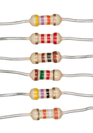
A resistor is a passive two-terminal electrical component that implements electrical resistance as a circuit element. In electronic circuits, resistors are used to reduce current flow, adjust signal levels, to divide voltages, bias active elements, and terminate transmission lines, among other uses. High-power resistors that can dissipate many watts of electrical power as heat may be used as part of motor controls, in power distribution systems, or as test loads for generators. Fixed resistors have resistances that only change slightly with temperature, time or operating voltage. Variable resistors can be used to adjust circuit elements, or as sensing devices for heat, light, humidity, force, or chemical activity.

Voltage, also known as electric pressure, electric tension, or (electric) potential difference, is the difference in electric potential between two points. In a static electric field, it corresponds to the work needed per unit of charge to move a test charge between the two points. In the International System of Units, the derived unit for voltage is named volt.

The volt is the unit of electric potential, electric potential difference (voltage), and electromotive force in the International System of Units (SI). It is named after the Italian physicist Alessandro Volta (1745–1827).
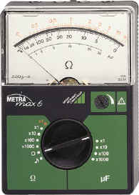
An ohmmeter is an electrical instrument that measures electrical resistance. Multimeters also function as ohmmeters when in resistance-measuring mode. An ohmmeter applies current to the circuit or component whose resistance is to be measured. It then measures the resulting voltage and calculates the resistance using Ohm’s law .

In electromagnetism and electronics, electromotive force is an energy transfer to an electric circuit per unit of electric charge, measured in volts. Devices called electrical transducers provide an emf by converting other forms of energy into electrical energy. Other electrical equipment also produce an emf, such as batteries, which convert chemical energy, and generators, which convert mechanical energy. This energy conversion is achieved by physical forces applying physical work on electric charges. However, electromotive force itself is not a physical force, and for the current ISO/IEC standards consider the term deprecated, favoring the names source voltage or source tension instead.

In direct-current circuit theory, Norton's theorem, also called the Mayer–Norton theorem, is a simplification that can be applied to networks made of linear time-invariant resistances, voltage sources, and current sources. At a pair of terminals of the network, it can be replaced by a current source and a single resistor in parallel.

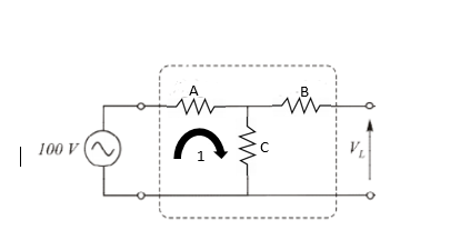
As originally stated in terms of direct-current resistive circuits only, Thévenin's theorem states that "Any linear electrical network containing only voltage sources, current sources and resistances can be replaced at terminals A–B by an equivalent combination of a voltage source Vth in a series connection with a resistance Rth."

Two-terminal components and electrical networks can be connected in series or parallel. The resulting electrical network will have two terminals, and itself can participate in a series or parallel topology. Whether a two-terminal "object" is an electrical component or an electrical network is a matter of perspective. This article will use "component" to refer to a two-terminal "object" that participate in the series/parallel networks.

A current source is an electronic circuit that delivers or absorbs an electric current which is independent of the voltage across it.
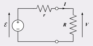
A practical electrical power source which is a linear electric circuit may, according to Thévenin's theorem, be represented as an ideal voltage source in series with an impedance. This impedance is termed the internal resistance of the source. When the power source delivers current, the measured voltage output is lower than the no-load voltage; the difference is the voltage drop caused by the internal resistance. The concept of internal resistance applies to all kinds of electrical sources and is useful for analyzing many types of electrical circuits.
In an electrical system, a ground loop or earth loop occurs when two points of a circuit are intended to have the same ground reference potential but instead have a different potential between them. This is typically caused when enough current is flowing in the connection between the two ground points to produce a voltage drop and cause two points to be at different potentials. Current may be produced in a circular ground connection by electromagnetic induction.

A voltage source is a two-terminal device which can maintain a fixed voltage. An ideal voltage source can maintain the fixed voltage independent of the load resistance or the output current. However, a real-world voltage source cannot supply unlimited current.
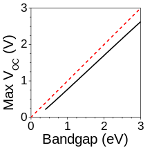
The photovoltaic effect is the generation of voltage and electric current in a material upon exposure to light. It is a physical and chemical phenomenon.
Mathematical methods are integral to the study of electronics.
A current–voltage characteristic or I–V curve is a relationship, typically represented as a chart or graph, between the electric current through a circuit, device, or material, and the corresponding voltage, or potential difference across it.
The superposition theorem is a derived result of the superposition principle suited to the network analysis of electrical circuits. The superposition theorem states that for a linear system the response in any branch of a bilateral linear circuit having more than one independent source equals the algebraic sum of the responses caused by each independent source acting alone, where all the other independent sources are replaced by their internal impedances.

The theory of solar cells explains the process by which light energy in photons is converted into electric current when the photons strike a suitable semiconductor device. The theoretical studies are of practical use because they predict the fundamental limits of a solar cell, and give guidance on the phenomena that contribute to losses and solar cell efficiency.
In electrical engineering, current sensing is any one of several techniques used to measure electric current. The measurement of current ranges from picoamps to tens of thousands of amperes. The selection of a current sensing method depends on requirements such as magnitude, accuracy, bandwidth, robustness, cost, isolation or size. The current value may be directly displayed by an instrument, or converted to digital form for use by a monitoring or control system.
This glossary of electrical and electronics engineering is a list of definitions of terms and concepts related specifically to electrical engineering and electronics engineering. For terms related to engineering in general, see Glossary of engineering.