Parity bit

Last updated
7 bits of data
(count of 1-bits)8 bits including parity
evenodd
000000000000000000000001
101000131010001110100010
110100141101001011010011
111111171111111111111110

A parity bit, or check bit, is a bit added to a string of binary code. Parity bits are a simple form of error detecting code. Parity bits are generally applied to the smallest units of a communication protocol, typically 8-bit octets (bytes), although they can also be applied separately to an entire message string of bits.

Contents

The parity bit ensures that the total number of 1-bits in the string is even or odd. [1] Accordingly, there are two variants of parity bits: even parity bit and odd parity bit. In the case of even parity, for a given set of bits, the bits whose value is 1 are counted. If that count is odd, the parity bit value is set to 1, making the total count of occurrences of 1s in the whole set (including the parity bit) an even number. If the count of 1s in a given set of bits is already even, the parity bit's value is 0. In the case of odd parity, the coding is reversed. For a given set of bits, if the count of bits with a value of 1 is even, the parity bit value is set to 1 making the total count of 1s in the whole set (including the parity bit) an odd number. If the count of bits with a value of 1 is odd, the count is already odd so the parity bit's value is 0. Even parity is a special case of a cyclic redundancy check (CRC), where the 1-bit CRC is generated by the polynomial x+1.

Parity

In mathematics parity can refer to the evenness or oddness of an integer, which, when written in its binary form, can be determined just by examining only its least significant bit.

In information technology parity refers to the evenness or oddness, given any set of binary digits, of the number of those bits with value one. Because parity is determined by the state of every one of the bits, this property of parity—being dependent upon all the bits and changing its value from even to odd parity if any one bit changes—allows for its use in error detection and correction schemes.

In telecommunications the parity referred to by some protocols is for error-detection. The transmission medium is preset, at both end points, to agree on either odd parity or even parity. For each string of bits ready to transmit (data packet) the sender calculates its parity bit, zero or one, to make it conform to the agreed parity, even or odd. The receiver of that packet first checks that the parity of the packet as a whole is in accordance with the preset agreement, then, if there was a parity error in that packet, requests a retransmission of that packet.

In computer science the parity stripe or parity disk in a RAID provides error-correction. Parity bits are written at the rate of one parity bit per n bits, where n is the number of disks in the array. When a read error occurs, each bit in the error region is recalculated from its set of n bits. In this way, using one parity bit creates "redundancy" for a region from the size of one bit to the size of one disk. See § Redundant Array of Independent Disks below.

In electronics, transcoding data with parity can be very efficient, as XOR gates output what is equivalent to a check bit that creates an even parity, and XOR logic design easily scales to any number of inputs. XOR and AND structures comprise the bulk of most integrated circuitry.

Error detection

If an odd number of bits (including the parity bit) are transmitted incorrectly, the parity bit will be incorrect, thus indicating that a parity error occurred in the transmission. The parity bit is suitable only for detecting errors; it cannot correct any errors, as there is no way to determine the particular bit that is corrupted. The data must be discarded entirely, and retransmitted from scratch. On a noisy transmission medium, successful transmission can therefore take a long time or even never occur. However, parity has the advantage that it uses only a single bit and requires only a number of XOR gates to generate. See Hamming code for an example of an error-correcting code.

Parity bit checking is used occasionally for transmitting ASCII characters, which have 7 bits, leaving the 8th bit as a parity bit.

For example, the parity bit can be computed as follows. Assume Alice and Bob are communicating and Alice wants to send Bob the simple 4-bit message 1001.

Type of bit paritySuccessful transmission scenario
Even parity

Alice wants to transmit: 1001 and 1011

Alice computes parity bit value:
1+0+0+1 (mod 2) = 0
1+0+1+1 (mod 2) = 1

Alice adds parity bit and sends:
10010 and 10111

Bob receives: 10010 and 10111

Bob computes parity:
1+0+0+1+0 (mod 2) = 0
1+0+1+1+1 (mod 2) = 0

Bob reports correct transmission after observing expected even result.

Odd parity

Alice wants to transmit: 1001 and 1011

Alice computes parity bit value:
1+0+0+1 (+ 1 mod 2) = 1
1+0+1+1 (+ 1 mod 2) = 0

Alice adds parity bit and sends:
10011 and 10110

Bob receives: 10011 and 10110

Bob computes overall parity:
1+0+0+1+1 (mod 2) = 1
1+0+1+1+0 (mod 2) = 1

Bob reports correct transmission after observing expected odd result.

This mechanism enables the detection of single bit errors, because if one bit gets flipped due to line noise, there will be an incorrect number of ones in the received data. In the two examples above, Bob's calculated parity value matches the parity bit in its received value, indicating there are no single bit errors. Consider the following example with a transmission error in the second bit using XOR:

Type of bit parity errorFailed transmission scenario
Even parity

Error in the second bit

Alice wants to transmit: 1001

Alice computes parity bit value: 1^0^0^1 = 0

Alice adds parity bit and sends: 10010

...TRANSMISSION ERROR...

Bob receives: 11010

Bob computes overall parity: 1^1^0^1^0 = 1

Bob reports incorrect transmission after observing unexpected odd result.

Even parity

Error in the parity bit

Alice wants to transmit: 1001

Alice computes even parity value: 1^0^0^1 = 0

Alice sends: 10010

...TRANSMISSION ERROR...

Bob receives: 10011

Bob computes overall parity: 1^0^0^1^1 = 1

Bob reports incorrect transmission after observing unexpected odd result.

There is a limitation to parity schemes. A parity bit is guaranteed to detect only an odd number of bit errors. If an even number of bits have errors, the parity bit records the correct number of ones even though the data is corrupt. (See also error detection and correction.) Consider the same example as before but with an even number of corrupted bits:

Type of bit parity errorFailed transmission scenario
Even parity

Two corrupted bits

Alice wants to transmit: 1001

Alice computes even parity value: 1^0^0^1 = 0

Alice sends: 10010

...TRANSMISSION ERROR...

Bob receives: 11011

Bob computes overall parity: 1^1^0^1^1 = 0

Bob reports correct transmission though actually incorrect.

Bob observes even parity, as expected, thereby failing to catch the two bit errors.

Usage

Because of its simplicity, parity is used in many hardware applications in which an operation can be repeated in case of difficulty, or simply detecting the error is helpful. For example, the SCSI and PCI buses use parity to detect transmission errors, and many microprocessor instruction caches include parity protection. Because the Instruction cache data is just a copy of the main memory, it can be disregarded and refetched if it is found to be corrupted.

In serial data transmission, a common format is 7 data bits, an even parity bit, and one or two stop bits. That format accommodates all the 7-bit ASCII characters in an 8-bit byte. Other formats are possible; 8 bits of data plus a parity bit can convey all 8-bit byte values.

In serial communication contexts, parity is usually generated and checked by interface hardware (such as a UART) and, on reception, the result made available to a processor such as the CPU (and so too, for instance, the operating system) via a status bit in a hardware register in the interface hardware. Recovery from the error is usually done by retransmitting the data, the details of which are usually handled by software (such as the operating system I/O routines).

When the total number of transmitted bits, including the parity bit, is even, odd parity has the advantage that both all-zeros and all-ones patterns are detected as errors. If the total number of bits is odd, only one of the patterns is detected as an error, and the choice can be made based on what the more common error is expected to be.

RAID array

Parity data is used by RAID arrays (redundant array of independent/inexpensive disks) to achieve redundancy. If a drive in the array fails, remaining data on the other drives can be combined with the parity data (using the Boolean XOR function) to reconstruct the missing data.

For example, suppose two drives in a three-drive RAID 4 array contained the following data:

Drive 1:01101101
Drive 2:11010100

To calculate parity data for the two drives, an XOR is performed on their data:

01101101
  XOR    11010100
10111001

The resulting parity data, 10111001, is then stored on Drive 3.

Should any of the three drives fail, the contents of the failed drive can be reconstructed on a replacement drive by subjecting the data from the remaining drives to the same XOR operation. If Drive 2 were to fail, its data could be rebuilt using the XOR results of the contents of the two remaining drives, Drive 1 and Drive 3:

Drive 1:01101101
Drive 3:10111001

as follows:

01101101Drive 1
XOR10111001Drive 3
11010100Reconstructed Drive 2

The result of that XOR calculation yields Drive 2's contents. 11010100 is then stored on Drive 2, fully repairing the array.

XOR logic is also equivalent to even parity (because a XOR b XOR c XOR ... may be treated as XOR(a,b,c,...), which is an n-ary operator that is true if and only if an odd number of arguments is true). So the same XOR concept above applies similarly to larger RAID arrays with parity, using any number of disks. In the case of a RAID 3 array of 12 drives, 11 drives participate in the XOR calculation shown above and yield a value that is then stored on the dedicated parity drive.

Extensions and variations on the parity bit mechanism "double," "dual," or "diagonal" parity, are used in RAID-DP.

History

A parity track was present on the first magnetic-tape data storage in 1951. Parity in this form, applied across multiple parallel signals, is known as a transverse redundancy check. This can be combined with parity computed over multiple bits sent on a single signal, a longitudinal redundancy check. In a parallel bus, there is one longitudinal redundancy check bit per parallel signal.

Parity was also used on at least some paper-tape (punched tape) data entry systems (which preceded magnetic-tape systems). On the systems sold by British company ICL (formerly ICT) the 1-inch-wide (25 mm) paper tape had 8 hole positions running across it, with the 8th being for parity. 7 positions were used for the data, e.g., 7-bit ASCII. The 8th position had a hole punched in it depending on the number of data holes punched.

See also

Related Research Articles

<span class="mw-page-title-main">Computer data storage</span> Storage of digital data readable by computers

Computer data storage is a technology consisting of computer components and recording media that are used to retain digital data. It is a core function and fundamental component of computers.

<span class="mw-page-title-main">Checksum</span> Data used to detect errors in other data

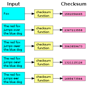
A checksum is a small-sized block of data derived from another block of digital data for the purpose of detecting errors that may have been introduced during its transmission or storage. By themselves, checksums are often used to verify data integrity but are not relied upon to verify data authenticity.

<span class="mw-page-title-main">Error detection and correction</span> Techniques that enable reliable delivery of digital data over unreliable communication channels

In information theory and coding theory with applications in computer science and telecommunication, error detection and correction (EDAC) or error control are techniques that enable reliable delivery of digital data over unreliable communication channels. Many communication channels are subject to channel noise, and thus errors may be introduced during transmission from the source to a receiver. Error detection techniques allow detecting such errors, while error correction enables reconstruction of the original data in many cases.

A cyclic redundancy check (CRC) is an error-detecting code commonly used in digital networks and storage devices to detect accidental changes to digital data. Blocks of data entering these systems get a short check value attached, based on the remainder of a polynomial division of their contents. On retrieval, the calculation is repeated and, in the event the check values do not match, corrective action can be taken against data corruption. CRCs can be used for error correction.

<span class="mw-page-title-main">Hamming code</span> Family of linear error-correcting codes

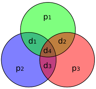
In computer science and telecommunication, Hamming codes are a family of linear error-correcting codes. Hamming codes can detect one-bit and two-bit errors, or correct one-bit errors without detection of uncorrected errors. By contrast, the simple parity code cannot correct errors, and can detect only an odd number of bits in error. Hamming codes are perfect codes, that is, they achieve the highest possible rate for codes with their block length and minimum distance of three. Richard W. Hamming invented Hamming codes in 1950 as a way of automatically correcting errors introduced by punched card readers. In his original paper, Hamming elaborated his general idea, but specifically focused on the Hamming(7,4) code which adds three parity bits to four bits of data.

In telecommunication, a longitudinal redundancy check (LRC), or horizontal redundancy check, is a form of redundancy check that is applied independently to each of a parallel group of bit streams. The data must be divided into transmission blocks, to which the additional check data is added.

RAID is a data storage virtualization technology that combines multiple physical disk drive components into one or more logical units for the purposes of data redundancy, performance improvement, or both. This is in contrast to the previous concept of highly reliable mainframe disk drives referred to as "single large expensive disk" (SLED).

The data link layer, or layer 2, is the second layer of the seven-layer OSI model of computer networking. This layer is the protocol layer that transfers data between nodes on a network segment across the physical layer. The data link layer provides the functional and procedural means to transfer data between network entities and may also provide the means to detect and possibly correct errors that can occur in the physical layer.

<span class="mw-page-title-main">Coding theory</span> Study of the properties of codes and their fitness

Coding theory is the study of the properties of codes and their respective fitness for specific applications. Codes are used for data compression, cryptography, error detection and correction, data transmission and data storage. Codes are studied by various scientific disciplines—such as information theory, electrical engineering, mathematics, linguistics, and computer science—for the purpose of designing efficient and reliable data transmission methods. This typically involves the removal of redundancy and the correction or detection of errors in the transmitted data.

<span class="mw-page-title-main">Data corruption</span> Errors in computer data that introduce unintended changes to the original data

Data corruption refers to errors in computer data that occur during writing, reading, storage, transmission, or processing, which introduce unintended changes to the original data. Computer, transmission, and storage systems use a number of measures to provide end-to-end data integrity, or lack of errors.

In coding theory, an erasure code is a forward error correction (FEC) code under the assumption of bit erasures, which transforms a message of k symbols into a longer message with n symbols such that the original message can be recovered from a subset of the n symbols. The fraction r = k/n is called the code rate. The fraction k’/k, where k’ denotes the number of symbols required for recovery, is called reception efficiency. The recovery algorithm expects that it is known which of the n symbols are lost — unlike forward error correction codes.

XOR gate is a digital logic gate that gives a true output when the number of true inputs is odd. An XOR gate implements an exclusive or from mathematical logic; that is, a true output results if one, and only one, of the inputs to the gate is true. If both inputs are false (0/LOW) or both are true, a false output results. XOR represents the inequality function, i.e., the output is true if the inputs are not alike otherwise the output is false. A way to remember XOR is "must have one or the other but not both".

Binary Synchronous Communication is an IBM character-oriented, half-duplex link protocol, announced in 1967 after the introduction of System/360. It replaced the synchronous transmit-receive (STR) protocol used with second generation computers. The intent was that common link management rules could be used with three different character encodings for messages.

In computer main memory, auxiliary storage and computer buses, data redundancy is the existence of data that is additional to the actual data and permits correction of errors in stored or transmitted data. The additional data can simply be a complete copy of the actual data, or only select pieces of data that allow detection of errors and reconstruction of lost or damaged data up to a certain level.

In computer storage, the standard RAID levels comprise a basic set of RAID configurations that employ the techniques of striping, mirroring, or parity to create large reliable data stores from multiple general-purpose computer hard disk drives (HDDs). The most common types are RAID 0 (striping), RAID 1 (mirroring) and its variants, RAID 5, and RAID 6. Multiple RAID levels can also be combined or nested, for instance RAID 10 or RAID 01. RAID levels and their associated data formats are standardized by the Storage Networking Industry Association (SNIA) in the Common RAID Disk Drive Format (DDF) standard. The numerical values only serve as identifiers and do not signify performance, reliability, generation, or any other metric.

Although all RAID implementations differ from the specification to some extent, some companies and open-source projects have developed non-standard RAID implementations that differ substantially from the standard. Additionally, there are non-RAID drive architectures, providing configurations of multiple hard drives not referred to by RAID acronyms.

The cyclic redundancy check (CRC) is based on division in the ring of polynomials over the finite field GF(2), that is, the set of polynomials where each coefficient is either zero or one, and arithmetic operations wrap around.

<span class="mw-page-title-main">Computation of cyclic redundancy checks</span> Overview of the computation of cyclic redundancy checks

Computation of a cyclic redundancy check is derived from the mathematics of polynomial division, modulo two. In practice, it resembles long division of the binary message string, with a fixed number of zeroes appended, by the "generator polynomial" string except that exclusive or operations replace subtractions. Division of this type is efficiently realised in hardware by a modified shift register, and in software by a series of equivalent algorithms, starting with simple code close to the mathematics and becoming faster through byte-wise parallelism and space–time tradeoffs.

A parity drive is a hard drive used in a RAID array to provide fault tolerance. For example, RAID 3 uses a parity drive to create a system that is both fault tolerant and, because of data striping, fast. Basically, a single data bit is added to the end of a data block to ensure the number of bits in the message is either odd or even.

ZFS is a file system with volume management capabilities. It began as part of the Sun Microsystems Solaris operating system in 2001. Large parts of Solaris – including ZFS – were published under an open source license as OpenSolaris for around 5 years from 2005 before being placed under a closed source license when Oracle Corporation acquired Sun in 2009–2010. During 2005 to 2010, the open source version of ZFS was ported to Linux, Mac OS X and FreeBSD. In 2010, the illumos project forked a recent version of OpenSolaris, including ZFS, to continue its development as an open source project. In 2013, OpenZFS was founded to coordinate the development of open source ZFS. OpenZFS maintains and manages the core ZFS code, while organizations using ZFS maintain the specific code and validation processes required for ZFS to integrate within their systems. OpenZFS is widely used in Unix-like systems.

References

  1. Ziemer, RodgerE.; Tranter, William H. (17 March 2014). Principles of communication : systems, modulation, and noise (Seventh ed.). Hoboken, New Jersey. ISBN   9781118078914. OCLC   856647730.{{cite book}}: CS1 maint: location missing publisher (link)