Precision approach path indicator

Last updated
The PAPI can be seen to the right (non-standard) side of the runway. The aircraft is slightly below the glideslope. PAPI Jersey Airport.JPG
The PAPI can be seen to the right (non-standard) side of the runway. The aircraft is slightly below the glideslope.

A precision approach path indicator (PAPI) is a system of lights on the side of an airport runway threshold that provides visual descent guidance information during final approach. It is generally located on the left-hand side of the runway approximately 300 meters beyond the landing threshold of the runway.

Contents

Design and installation

A typical engineering design specification for a PAPI light unit is shown below:

Schematic diagram of longitudinal section
1 = Axis datum
2 = Light source
3 = Red filter
4 = Lenses
5 / 6 = Light beam- white/red PAPI-Section.svg
Schematic diagram of longitudinal section
1 = Axis datum
2 = Light source
3 = Red filter
4 = Lenses
5 / 6 = Light beam- white/red

Optical construction:

Each light unit consists of one or more light sources, red filters and lenses. A color filter may not be necessary with colored LED lights. Each light unit emits a high-intensity beam. The lower segment of the beam is red, and the upper part is white. The transition between the two colours must take place over an angle not greater than three minutes of arc. This characteristic makes the color change very conspicuous, a key feature of the PAPI signal. To form the PAPI guidance signal, the color transition boundaries of the four units are fixed at different angles. The lowest angle is used for the unit furthest from the runway, the highest for the unit nearest to the runway. The designated glideslope is midway between the second and third light unit settings.

A PAPI installation consists of a bar of four units. Units should be frangible but not susceptible to jet blast. The inner edge of the PAPI installation should be situated 15 meters from the runway edge, and not closer than 14 meters to any runway or taxiway. The units should be spaced 9 meters apart. An abbreviated system, A-PAPI, can be used for some categories of aircraft operations. It consists of two units with the inner unit located 10 meters from the runway edge. [1]

The PAPI should be located on the left-hand side of the runway at right angles to the runway center line, although can be located on the right-hand side of the runway if required. The red lights are always on the side closest to the runway. If the PAPI is on the right-hand side of the runway (non-standard), the red lights will be on the left. At some locations PAPIs are installed on both sides of the runway but this level of provision is beyond the requirements of ICAO.

The optimum distance from the runway threshold depends on the wheel clearance over the threshold of the types of aircraft expected to land on the runway; compatibility with non-visual glide paths such as ILS down to the minimum possible range and height; and any difference in elevation between the PAPI installation and the runway threshold. This optimum distance may be adjusted depending on runway length and obstacle clearance. Harmonisation between PAPIs and an ILS system must take into account the distance between eye height and ILS receiver height for various aircraft. [1] :8–33

For a typical 3 degree approach slope, PAPI lights should be angled as follows: 3°30', 3°10', 2°50', 2°30' (3.50°, 3.17°, 2.83°, 2.50°). [1] :8–36

Interpretation

Comparison of PAPI, VASI, and OLS meatball and datum lights (not to scale) Comparison visual landing systems.svg
Comparison of PAPI, VASI, and OLS meatball and datum lights (not to scale)

The ratio of white to red lights seen is dependent on the angle of approach to the runway. Above the designated glide slope a pilot will see more white lights than red; below the ideal angle more red lights than white will be seen. At the optimum approach angle the ratio of white to red lights will be equal, for most aircraft.

Student pilots in initial training may use the mnemonic

until they are used to the lights' meaning.

Individual precision approach path indicator PAPI M39.jpg
Individual precision approach path indicator

PAPIs are calibrated relative to the Minimum Eye Height over Threshold (MEHT). [1] For certain aircraft with a low pilot eye height, the pilot will see a "slightly low" indication even though they are on the ILS glideslope. [2] Pilot eye height is usually above the ILS receiver antenna. [3] Concorde had a particularly high eye height because the main undercarriage was so far behind the cockpit, so the pilots needed to land with a "slightly high" indication. [4]

The light characteristics of all light units are identical. In good visibility conditions the guidance information can be used at ranges up to 5 miles (8.0 km) by day and night. At night the light bars can be seen at ranges of at least 20 miles (32 km).

PAPI systems are readily available from airfield lighting manufacturers worldwide. PAPI is normally operated by air traffic control (ATC). If ATC services are not normally provided at an aerodrome, PAPI along with other airport lights may be activated by the pilot by keying the aircraft microphone with the aircraft's communication radio tuned to the CTAF or dedicated pilot controlled lighting (PCL) frequency.

History

The precision approach path indicator system was first devised in 1974 by Tony Smith and David Johnson at the Royal Aircraft Establishment in Bedford, England. It took them a further two years to fully develop the technology. Engineering firm Research Engineers (RE) were also heavily involved in the project, having produced and supplied PAPI units for the first trials that were conducted. The same design is still in use today. [5]

Smith and Johnson's work was honoured by a commendation from the RAE, a Fellowship from the Aeronautical Society, an award from the American Flight Safety Foundation, and a Gold Medal from the British Guild of Air Pilots.[ citation needed ]

PAPIs were used by NASA's Space Shuttle for its safe landing, for which Johnson was interviewed by UK local news media and TV.[ citation needed ]

An earlier glideslope indicator system, the visual approach slope indicator (VASI), only provided guidance down to heights of 60 metres (200 ft) whereas PAPI provides guidance down to flare initiation (typically 15 metres, or 50 ft).[ citation needed ]

2008 saw the advent of new PAPI devices manufactured using solid state LED lamps instead of incandescent lamps. The LEDs produce sufficient brightness to satisfy ICAO light intensity and beamspread standards, and average lifetime with the LED based systems is 50,000 hours or more. By using LEDs, the device's power consumption is lowered considerably. The LED systems run internally on DC voltage, so the DC voltage requirements, along with the LEDs' inherently low power consumption, now allow for solar-powered PAPIs, enabling them to function completely independently of a power grid. [6]

The PAPI system is co-opted for use by the Final Approach Runway Occupancy Signal (FAROS) system being introduced [7] by several major airports in the United States for the purpose of allowing pilots to resolve a runway incursion without requiring a priori notice of an occupied runway from the control tower. In FAROS, automated line-of-sight runway sensors detect if a vehicle has committed a runway incursion, and if so, will flash the PAPI lights to alert the pilot of an aircraft on final approach that the runway is currently occupied. The pilot then becomes responsible for resolving the conflict by notifying the air traffic controller and executing a go-around. Once the tower has ascertained that the runway has been cleared, the ground controller resets the PAPI so that landing operations may resume normally. [8] [9]

See also

Related Research Articles

<span class="mw-page-title-main">Runway</span> Area of surface used by aircraft to takeoff from and land on

According to the International Civil Aviation Organization (ICAO), a runway is a "defined rectangular area on a land aerodrome prepared for the landing and takeoff of aircraft". Runways may be a human-made surface or a natural surface. Runways, taxiways and ramps, are sometimes referred to as "tarmac", though very few runways are built using tarmac. Takeoff and landing areas defined on the surface of water for seaplanes are generally referred to as waterways. Runway lengths are now commonly given in meters worldwide, except in North America where feet are commonly used.

<span class="mw-page-title-main">Instrument landing system</span> Ground-based visual aid for landing

In aviation, the instrument landing system (ILS) is a precision radio navigation system that provides short-range guidance to aircraft to allow them to approach a runway at night or in bad weather. In its original form, it allows an aircraft to approach until it is 200 feet (61 m) over the ground, within a 12 mile (800 m) of the runway. At that point the runway should be visible to the pilot; if it is not, they perform a missed approach. Bringing the aircraft this close to the runway dramatically increases the range of weather conditions in which a safe landing can be made. Other versions of the system, or "categories", have further reduced the minimum altitudes, runway visual ranges (RVRs), and transmitter and monitoring configurations designed depending on the normal expected weather patterns and airport safety requirements.

Aviation is the design, development, production, operation, and use of aircraft, especially heavier-than-air aircraft. Articles related to aviation include:

The visual approach slope indicator (VASI) is a system of lights on the side of an airport runway threshold that provides visual descent guidance information during final approach. These lights may be visible from up to 8 kilometres (5.0 mi) during the day and up to 32 kilometres (20 mi) or more at night.

Pilot-controlled lighting (PCL), also known as aircraft radio control of aerodrome lighting (ARCAL) or pilot-activated lighting (PAL), is a system that allows aircraft pilots to control the lighting of an airport or airfield's approach lights, runway edge lights, and taxiways via radio.

<span class="mw-page-title-main">Instrument approach</span> Aircraft landing procedure

In aviation, an instrument approach or instrument approach procedure (IAP) is a series of predetermined maneuvers for the orderly transfer of an aircraft operating under instrument flight rules from the beginning of the initial approach to a landing, or to a point from which a landing may be made visually. These approaches are approved in the European Union by EASA and the respective country authorities and in the United States by the FAA or the United States Department of Defense for the military. The ICAO defines an instrument approach as "a series of predetermined maneuvers by reference to flight instruments with specific protection from obstacles from the initial approach fix, or where applicable, from the beginning of a defined arrival route to a point from which a landing can be completed and thereafter, if landing is not completed, to a position at which holding or en route obstacle clearance criteria apply."

<span class="mw-page-title-main">Autoland</span> Automated aircraft landing procedure

In aviation, autoland describes a system that fully automates the landing procedure of an aircraft's flight, with the flight crew supervising the process. Such systems enable airliners to land in weather conditions that would otherwise be dangerous or impossible to operate in.

<span class="mw-page-title-main">Runway visual range</span> Measure of aircraft visual distance

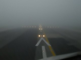
In aviation, the runway visual range (RVR) is the distance over which a pilot of an aircraft on the centreline of the runway can see the runway surface markings delineating the runway or the lights delineating the runway or identifying its centre line. RVR is normally expressed in meters or feet. RVR is used to determine the landing and takeoff conditions for aircraft pilots, as well as the type of operational visual aids used at the airport.

<span class="mw-page-title-main">Precision approach radar</span> Type of radar guidance system

Precision approach radar orPAR is a type of radar guidance system designed to provide lateral and vertical guidance to an aircraft pilot for landing, until the landing threshold is reached. Controllers monitoring the PAR displays observe each aircraft's position and issue instructions to the pilot that keep the aircraft on course and glidepath during final approach. After the aircraft reaches the decision height (DH) or decision altitude (DA), further guidance is advisory only. The overall concept is known as ground-controlled approach (GCA), and this name was also used to refer to the radar systems in the early days of its development.

<span class="mw-page-title-main">Marker beacon</span> Type of VHF radio beacon used in aviation

A marker beacon is a particular type of VHF radio beacon used in aviation, usually in conjunction with an instrument landing system (ILS), to give pilots a means to determine position along an established route to a destination such as a runway.

<span class="mw-page-title-main">Transponder landing system</span> All-weather, precision landing system

A transponder landing system (TLS) is an all-weather, precision landing system that uses existing airborne transponder and instrument landing system (ILS) equipment to create a precision approach at a location where an ILS would normally not be available.

<span class="mw-page-title-main">Perth Airport (Scotland)</span> Airport in Scone, Scotland

Perth Airport is a general-aviation airport located at New Scone, 3 nautical miles northeast of Perth, Scotland. The airport is used by private and business aircraft, and for pilot training. There are no commercial scheduled flights from the airport.

<span class="mw-page-title-main">Approach lighting system</span> Runway lighting installed on the approach end which extends beyond the runway

An approach lighting system (ALS) is a lighting system installed on the approach end of an airport runway and consisting of a series of lightbars, strobe lights, or a combination of the two that extends outward from the runway end. ALS usually serves a runway that has an instrument approach procedure (IAP) associated with it and allows the pilot to visually identify the runway environment and align the aircraft with the runway upon arriving at a prescribed point on an approach.

In aviation, a ground-controlled approach (GCA) is a type of service provided by air-traffic controllers whereby they guide aircraft to a safe landing, including in adverse weather conditions, based on primary radar images. Most commonly, a GCA uses information from either a precision approach radar or an airport surveillance radar. The term GCA may refer to any type of ground radar guided approach such as a PAR, PAR without glideslope or ASR. When both vertical and horizontal guidance from the PAR is given, the approach is termed a precision approach. If no PAR glidepath is given, even if PAR equipment is used for lateral guidance, it is considered a non-precision approach.

<span class="mw-page-title-main">Final approach</span> Final stage in an aircrafts approach to landing

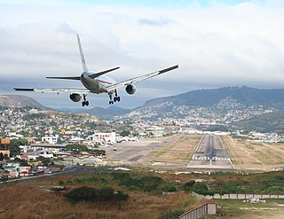
In aeronautics, the final approach is the last leg in an aircraft's approach to landing, when the aircraft is lined up with the runway and descending for landing. In aviation radio terminology, it is often shortened to "final".

<span class="mw-page-title-main">Optical landing system</span> Visual landing system used on US Navy aircraft carriers

An optical landing system (OLS) is used to give glidepath information to pilots in the terminal phase of landing on an aircraft carrier.

<span class="mw-page-title-main">Turkish Airlines Flight 634</span> 2003 aviation accident

Turkish Airlines Flight 634 was a scheduled domestic passenger flight from Turkish Airlines' hub at Istanbul Atatürk Airport to Diyarbakır Airport in southeastern Turkey. On 8 January 2003 at 20:19 EET, the aircraft operating the flight, a British Aerospace Avro RJ100, struck the ground on final approach approximately 900 metres (3,000 ft) short of the runway threshold during inclement weather conditions. In the following collision with a slope, a post-crash fire broke out, killing 75 of the 80 occupants, including the entire crew. This is the deadliest aviation accident to involve the BAe 146.

Visual Glide Slope Indicator or Visual Glideslope Indicator (VGSI) is a ground device that uses lights to assist a pilot in landing an airplane at an airport. The lights define a vertical approach path during the final approach to a runway and can help the pilot determine if the airplane is too high or too low for an optimum landing.

The Blind Landing Experimental Unit, abbreviated BLEU, was a unit of the British government tasked with creating an early autolanding system for military and civilian aircraft from the late 1940s until the mid-1960s.

<span class="mw-page-title-main">Enhanced flight vision system</span> Airborne system with imaging sensors

An enhanced flight vision system is an airborne system which provides an image of the scene and displays it to the pilot, in order to provide an image in which the scene and objects in it can be better detected. In other words, an EFVS is a system which provides the pilot with an image which is better than unaided human vision. An EFVS includes imaging sensors such as a color camera, infrared camera or radar, and typically a display for the pilot, which can be a head-mounted display or head-up display. An EFVS may be combined with a synthetic vision system to create a combined vision system.

References

  1. 1 2 3 4 ICAO Doc 9157, Aerodrome Design Manual. Fifth edition, 2021. Part 4, Visual Aids. Chapter 8 (PDF). ICAO. Archived from the original (PDF) on 1 March 2023. Retrieved 1 March 2023.
  2. https://publicapps.caa.co.uk/docs/33/CAP637%20Visual%20Aids%20Handbook.pdf [ bare URL PDF ]
  3. https://www.airbus.com/sites/g/files/jlcbta136/files/2021-11/Airbus-Aircraft-Data-for-Visual-Aids-Calibration-v5.0.pdf [ bare URL PDF ]
  4. Bannister, Mike (29 September 2022). Concorde: The thrilling account of history's most extraordinary airliner. Random House. ISBN   978-0-241-55702-0 . Retrieved 1 March 2023.
  5. "Research Engineers PAPI". Archived from the original on 2014-01-25. Retrieved 2017-05-14.
  6. "Solar PAPI & APAPI (Precision Approach Path Indicator)". Archived from the original on 2011-12-30. Retrieved 2012-04-10.
  7. "Aeronautical Information Manual (AIM) - Page 87". www.faraim.org. Retrieved 2019-12-24.
  8. "Final Approach Runway Occupancy Signal (FAROS) - Animation". Archived from the original on 2010-02-09. Retrieved 2010-06-07.
  9. "Section 1. Airport Lighting Aids" . Retrieved 2019-09-19.