Related Research Articles
Processor design is a subfield of computer engineering and electronics engineering (fabrication) that deals with creating a processor, a key component of computer hardware.

An integrated circuit or monolithic integrated circuit is a set of electronic circuits on one small flat piece of semiconductor material, usually silicon. Large numbers of tiny MOSFETs integrate into a small chip. This results in circuits that are orders of magnitude smaller, faster, and less expensive than those constructed of discrete electronic components. The IC's mass production capability, reliability, and building-block approach to integrated circuit design has ensured the rapid adoption of standardized ICs in place of designs using discrete transistors. ICs are now used in virtually all electronic equipment and have revolutionized the world of electronics. Computers, mobile phones, and other digital home appliances are now inextricable parts of the structure of modern societies, made possible by the small size and low cost of ICs such as modern computer processors and microcontrollers.
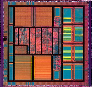
Very large-scale integration (VLSI) is the process of creating an integrated circuit (IC) by combining millions of MOS transistors onto a single chip. VLSI began in the 1970s when MOS integrated circuit chips were widely adopted, enabling complex semiconductor and telecommunication technologies to be developed. The microprocessor and memory chips are VLSI devices. Before the introduction of VLSI technology, most ICs had a limited set of functions they could perform. An electronic circuit might consist of a CPU, ROM, RAM and other glue logic. VLSI enables IC designers to add all of these into one chip.

Digital electronics is a field of electronics involving the study of digital signals with discrete states and the engineering of devices that use or produce them. This is in contrast to analog electronics and analog signals, which use continuous signals.

The metal–oxide–semiconductor field-effect transistor, also known as the metal–oxide–silicon transistor, is a type of insulated-gate field-effect transistor that is fabricated by the controlled oxidation of a semiconductor, typically silicon. The voltage of the gate terminal determines the electrical conductivity of the device; this ability to change conductivity with the amount of applied voltage can be used for amplifying or switching electronic signals.
Transistor–transistor logic (TTL) is a logic family built from bipolar junction transistors. Its name signifies that transistors perform both the logic function and the amplifying function, as opposed to resistor–transistor logic (RTL) or diode–transistor logic (DTL).
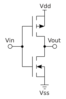
Complementary metal–oxide–semiconductor, also known as complementary-symmetry metal–oxide–semiconductor (COS-MOS), is a type of metal–oxide–semiconductor field-effect transistor (MOSFET) fabrication process that uses complementary and symmetrical pairs of p-type and n-type MOSFETs for logic functions. CMOS technology is used for constructing integrated circuit (IC) chips, including microprocessors, microcontrollers, memory chips, and other digital logic circuits. CMOS technology is also used for analog circuits such as image sensors, data converters, RF circuits, and highly integrated transceivers for many types of communication.
In automata theory, sequential logic is a type of logic circuit whose output depends not only on the present value of its input signals but on the sequence of past inputs, the input history as well. This is in contrast to combinational logic, whose output is a function of only the present input. That is, sequential logic has state (memory) while combinational logic does not.

An application-specific integrated circuit is an integrated circuit (IC) chip customized for a particular use, rather than intended for general-purpose use. For example, a chip designed to run in a digital voice recorder or a high-efficiency video codec is an ASIC. Application-specific standard product (ASSP) chips are intermediate between ASICs and industry standard integrated circuits like the 7400 series or the 4000 series. ASIC chips are typically fabricated using metal-oxide-semiconductor (MOS) technology, as MOS integrated circuit chips.
Electronic design automation (EDA), also referred to as electronic computer-aided design (ECAD), is a category of software tools for designing electronic systems such as integrated circuits and printed circuit boards. The tools work together in a design flow that chip designers use to design and analyze entire semiconductor chips. Since a modern semiconductor chip can have billions of components, EDA tools are essential for their design; this article in particular describes EDA specifically with respect to integrated circuits (ICs).
In computer engineering, a logic family is one of two related concepts:

In computer engineering, microarchitecture, also called computer organization and sometimes abbreviated as µarch or uarch, is the way a given instruction set architecture (ISA) is implemented in a particular processor. A given ISA may be implemented with different microarchitectures; implementations may vary due to different goals of a given design or due to shifts in technology.
Asynchronous circuit is a sequential digital logic circuit that doesn't use a global clock circuit or signal generator to synchronize its components. instead, the components are driven by handshaking which indicates completion of the instructions. Handshaking works by simple data transfer protocols. Many synchronous circuits were developed in early 1950s as part of bigger asynchronous systems. Asynchronous circuits and theory surrounding is a part of several steps in integrated circuit design, a field of digital electronics engineering.
In semiconductor design, standard cell methodology is a method of designing application-specific integrated circuits (ASICs) with mostly digital-logic features. Standard cell methodology is an example of design abstraction, whereby a low-level very-large-scale integration (VLSI) layout is encapsulated into an abstract logic representation.
Logic simulation is the use of simulation software to predict the behavior of digital circuits and hardware description languages. Simulation can be performed at varying degrees of physical abstraction, such as at the transistor level, gate level, register-transfer level (RTL), electronic system-level (ESL), or behavioral level.
Power optimization is the use of electronic design automation tools to optimize (reduce) the power consumption of a digital design, such as that of an integrated circuit, while preserving the functionality.
In integrated circuit design, dynamic logic is a design methodology in combinatory logic circuits, particularly those implemented in MOS technology. It is distinguished from the so-called static logic by exploiting temporary storage of information in stray and gate capacitances. It was popular in the 1970s and has seen a recent resurgence in the design of high speed digital electronics, particularly computer CPUs. Dynamic logic circuits are usually faster than static counterparts, and require less surface area, but are more difficult to design. Dynamic logic has a higher toggle rate than static logic but the capacitive loads being toggled are smaller so the overall power consumption of dynamic logic may be higher or lower depending on various tradeoffs. When referring to a particular logic family, the dynamic adjective usually suffices to distinguish the design methodology, e.g. dynamic CMOS or dynamic SOI design.
An application-specific instruction set processor (ASIP) is a component used in system-on-a-chip design. The instruction set of an ASIP is tailored to benefit a specific application. This specialization of the core provides a tradeoff between the flexibility of a general purpose CPU and the performance of an ASIC.

In integrated circuit design, physical design is a step in the standard design cycle which follows after the circuit design. At this step, circuit representations of the components of the design are converted into geometric representations of shapes which, when manufactured in the corresponding layers of materials, will ensure the required functioning of the components. This geometric representation is called integrated circuit layout. This step is usually split into several sub-steps, which include both design and verification and validation of the layout.
In electronics, pass transistor logic (PTL) describes several logic families used in the design of integrated circuits. It reduces the count of transistors used to make different logic gates, by eliminating redundant transistors. Transistors are used as switches to pass logic levels between nodes of a circuit, instead of as switches connected directly to supply voltages. This reduces the number of active devices, but has the disadvantage that the difference of the voltage between high and low logic levels decreases at each stage. Each transistor in series is less saturated at its output than at its input. If several devices are chained in series in a logic path, a conventionally constructed gate may be required to restore the signal voltage to the full value. By contrast, conventional CMOS logic switches transistors so the output connects to one of the power supply rails, so logic voltage levels in a sequential chain do not decrease. Simulation of circuits may be required to ensure adequate performance.
References
- ↑ Kaeslin, Hubert (2008). Digital Integrated Circuit Design: From VLSI Architectures to CMOS Fabrication. Cambridge University Press. p. 747. ISBN 978-0-521-88267-5.
- ↑ Hyde, Randall (2004). Write Great Code: Understanding the Machine. No Starch Press. p. 228. ISBN 978-1-59327-003-2.