
Parallax is a displacement or difference in the apparent position of an object viewed along two different lines of sight and is measured by the angle or half-angle of inclination between those two lines. Due to foreshortening, nearby objects show a larger parallax than farther objects, so parallax can be used to determine distances.
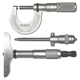
A micrometer, sometimes known as a micrometer screw gauge, is a device incorporating a calibrated screw widely used for accurate measurement of components in mechanical engineering and machining as well as most mechanical trades, along with other metrological instruments such as dial, vernier, and digital calipers. Micrometers are usually, but not always, in the form of calipers. The spindle is a very accurately machined screw and the object to be measured is placed between the spindle and the anvil. The spindle is moved by turning the ratchet knob or thimble until the object to be measured is lightly touched by both the spindle and the anvil.

Telemetry is the in situ collection of measurements or other data at remote points and their automatic transmission to receiving equipment (telecommunication) for monitoring. The word is derived from the Greek roots tele, 'remote', and metron, 'measure'. Systems that need external instructions and data to operate require the counterpart of telemetry: telecommand.

Surveying or land surveying is the technique, profession, art, and science of determining the terrestrial two-dimensional or three-dimensional positions of points and the distances and angles between them. These points are usually on the surface of the Earth, and they are often used to establish maps and boundaries for ownership, locations, such as the designed positions of structural components for construction or the surface location of subsurface features, or other purposes required by government or civil law, such as property sales.

A reticle, or reticule also known as a graticule, is a pattern of fine lines or markings built into the eyepiece of an optical device such as a telescopic sight, spotting scope, theodolite, optical microscope or the screen of an oscilloscope, to provide measurement references during visual inspections. Today, engraved lines or embedded fibers may be replaced by a digital image superimposed on a screen or eyepiece. Both terms may be used to describe any set of patterns used for aiding visual measurements and calibrations, but in modern use reticle is most commonly used for weapon sights, while graticule is more widely used for non-weapon measuring instruments such as oscilloscope display, astronomic telescopes, microscopes and slides, surveying instruments and other similar devices.
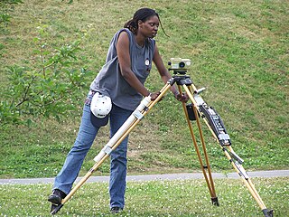
Levelling or leveling is a branch of surveying, the object of which is to establish or verify or measure the height of specified points relative to a datum. It is widely used in geodesy and cartography to measure vertical position with respect to a vertical datum, and in construction to measure height differences of construction artifacts.
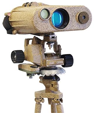
A laser rangefinder, also known as a laser telemeter, is a rangefinder that uses a laser beam to determine the distance to an object. The most common form of laser rangefinder operates on the time of flight principle by sending a laser pulse in a narrow beam towards the object and measuring the time taken by the pulse to be reflected off the target and returned to the sender. Due to the high speed of light, this technique is not appropriate for high precision sub-millimeter measurements, where triangulation and other techniques are often used. It is a type of scannerless lidar.

The term Jacob's staff is used to refer to several things, also known as cross-staff, a ballastella, a fore-staff, a ballestilla, or a balestilha. In its most basic form, a Jacob's staff is a stick or pole with length markings; most staffs are much more complicated than that, and usually contain a number of measurement and stabilization features. The two most frequent uses are:

Gun laying is the process of aiming an artillery piece or turret, such as a gun, howitzer, or mortar, on land, in air, or at sea, against surface or aerial targets. It may be laying for direct fire, where the gun is aimed similarly to a rifle, or indirect fire, where firing data is calculated and applied to the sights. The term includes automated aiming using, for example, radar-derived target data and computer-controlled guns.

A level is an optical instrument used to establish or verify points in the same horizontal plane in a process known as levelling. It is used in conjunction with a levelling staff to establish the relative height or levels of objects or marks. It is widely used in surveying and construction to measure height differences and to transfer, measure, and set heights of known objects or marks.

Stadiametric rangefinding, or the stadia method, is a technique of measuring distances with a telescopic instrument. The term stadia comes from a Greek unit of length Stadion which was the typical length of a sports stadium of the time. Stadiametric rangefinding is used for surveying and in the telescopic sights of firearms, artillery pieces, or tank guns, as well as some binoculars and other optics. It is still widely used in long-range military sniping, but in many professional applications it is being replaced with microwave, infrared, or laser rangefinding methods. Although much easier to use, electronic rangefinders can give away the shooter's position to a well-equipped adversary, and the need for accurate range estimation has existed for much longer than electronic rangefinders small and rugged enough to be suitable for military use.

Tacheometry is a system of rapid surveying, by which the horizontal and vertical positions of points on the Earth's surface relative to one another are determined using a tacheometer without using a chain or tape, or a separate levelling instrument. Instead of the pole normally employed to mark a point, a staff similar to a level staff is used. This is marked with heights from the base or foot, and is graduated according to the form of tacheometer in use.

A height finder is a ground-based aircraft altitude measuring device. Early height finders were optical range finder devices combined with simple mechanical computers, while later systems migrated to radar devices. The unique vertical oscillating motion of height finder radars led to them also being known as nodding radar. Devices combining both optics and radar were deployed by the U.S. Military.

A filar micrometer is a specialized eyepiece used in astronomical telescopes for astrometry measurements, in microscopes for specimen measurements, and in alignment and surveying telescopes for measuring angles and distances on nearby objects. "Filar" derives from the Latin filum ("thread"). It refers to the fine threads or wires used in the device.

A coincidence rangefinder or coincidence telemeter is a type of rangefinder that uses mechanical and optical principles to allow an operator to determine the distance to a visible object. There are subtypes split-image telemeter, inverted image, or double-image telemeter with different principles how two images in a single ocular are compared. Coincidence rangefinders were important elements of fire control systems for long-range naval guns and land-based coastal artillery circa 1890–1960. They were also used in rangefinder cameras.

A stereoscopic rangefinder or stereoscopic telemeter is an optical device that measures distance from the observer to a target, using the observer's capability of binocular vision. It looks similar to a coincidence rangefinder, which uses different principles and has only one eyepiece. German instruments tended to use the stereoscopic principle while British ones used coincidence.
A reflector sight or reflex sight is an optical sight that allows the user to look through a partially reflecting glass element and see an illuminated projection of an aiming point or some other image superimposed on the field of view. These sights work on the simple optical principle that anything at the focus of a lens or curved mirror will appear to be sitting in front of the viewer at infinity. Reflector sights employ some form of "reflector" to allow the viewer to see the infinity image and the field of view at the same time, either by bouncing the image created by lens off a slanted glass plate, or by using a mostly clear curved glass reflector that images the reticle while the viewer looks through the reflector. Since the reticle is at infinity it stays in alignment with the device to which the sight is attached regardless of the viewer's eye position, removing most of the parallax and other sighting errors found in simple sighting devices.
Length measurement, distance measurement, or range measurement (ranging) refers to the many ways in which length, distance, or range can be measured. The most commonly used approaches are the rulers, followed by transit-time methods and the interferometer methods based upon the speed of light.
Tree height is the vertical distance between the base of the tree and the tip of the highest branch on the tree, and is difficult to measure accurately. It is not the same as the length of the trunk. If a tree is leaning, the trunk length may be greater than the height of the tree. The base of the tree is where the projection of the pith (center) of the tree intersects the existing supporting surface upon which the tree is growing or where the seed sprouted. If the tree is growing on the side of a cliff, the base of the tree is at the point where the pith would intersect the cliff side. Roots extending down from that point would not add to the height of the tree. On a slope this base point is considered as halfway between the ground level at the upper and lower sides of the tree. Tree height can be measured in a number of ways with varying degrees of accuracy.

The depression range finder (DRF) was a fire control device used to determine the target's position by observing range and bearing and to calculate firing solutions when gun laying in coastal artillery. It was the main component of a vertical base rangefinding system. It was necessitated by the introduction of rifled artillery from the mid-19th century onwards, which had much greater ranges than the old smoothbore weapons and were consequently more difficult to aim accurately. The DRF was invented by Captain H.S.S. Watkin of the Royal Artillery in the 1870s and was adopted in 1881. It could provide both range and bearing information on a target. The device's inventor also developed a family of similar devices, among them the position finder, which used two telescopes as a horizontal base rangefinding system, around the same time; some of these were called electric position finders. Some position finders retained a depression range finding capability; some of these were called depression position finders. Watkin's family of devices were deployed in position finding cells, a type of fire control tower, often in configurations that allowed both horizontal base and vertical base rangefinding. Watkin's system included automatic electrical updating of range and bearing dials near the guns as the position finders were manipulated, and a system of remotely firing the guns electrically from the position finding cell. The improved system was trialled in 1885 and widely deployed in the 1890s. Functionally equivalent devices were developed for the United States Army Coast Artillery Corps and its predecessors, called depression position finders or azimuth instruments depending on function, adopted in 1896 and deployed widely beginning in the early 1900s as the Endicott program of modern coastal defences was built. These devices were also used by both countries to control submarine (underwater) minefields.


