Delta-v, symbolized as and pronounced delta-vee, as used in spacecraft flight dynamics, is a measure of the impulse per unit of spacecraft mass that is needed to perform a maneuver such as launching from or landing on a planet or moon, or an in-space orbital maneuver. It is a scalar that has the units of speed. As used in this context, it is not the same as the physical change in velocity of said spacecraft.

Gemini 8 was the sixth crewed spaceflight in NASA's Gemini program. It was launched on March 16, 1966, and was the 14th crewed American flight and the 22nd crewed spaceflight overall. The mission conducted the first docking of two spacecraft in orbit, but also suffered the first critical in-space system failure of a U.S. spacecraft which threatened the lives of the astronauts and required an immediate abort of the mission. The crew returned to Earth safely.

The Voskhod was a spacecraft built by the Soviet Union's space program for human spaceflight as part of the Voskhod programme. It was a development of and a follow-on to the Vostok spacecraft. Voskhod 1 was used for a three-man flight whereas Voskhod 2 had a crew of two. They consisted of a spherical descent module, which housed the cosmonauts, and instruments, and a conical equipment module, which contained propellant and the engine system. Voskhod was superseded by the Soyuz spacecraft in 1967.

The Apollo spacecraft was composed of three parts designed to accomplish the American Apollo program's goal of landing astronauts on the Moon by the end of the 1960s and returning them safely to Earth. The expendable (single-use) spacecraft consisted of a combined command and service module (CSM) and an Apollo Lunar Module (LM). Two additional components complemented the spacecraft stack for space vehicle assembly: a spacecraft–LM adapter (SLA) designed to shield the LM from the aerodynamic stress of launch and to connect the CSM to the Saturn launch vehicle and a launch escape system (LES) to carry the crew in the command module safely away from the launch vehicle in the event of a launch emergency.
A service module is a component of a crewed space capsule containing a variety of support systems used for spacecraft operations. Usually located in the uninhabited area of the spacecraft, the service module serves a storehouse of critical subsystems and supplies for the mission such as electrical systems, environmental control, and propellant tanks. The service module is jettisoned upon the completion of the mission, and usually burns up during atmospheric reentry.

The Apollo command and service module (CSM) was one of two principal components of the United States Apollo spacecraft, used for the Apollo program, which landed astronauts on the Moon between 1969 and 1972. The CSM functioned as a mother ship, which carried a crew of three astronauts and the second Apollo spacecraft, the Apollo Lunar Module, to lunar orbit, and brought the astronauts back to Earth. It consisted of two parts: the conical command module, a cabin that housed the crew and carried equipment needed for atmospheric reentry and splashdown; and the cylindrical service module which provided propulsion, electrical power and storage for various consumables required during a mission. An umbilical connection transferred power and consumables between the two modules. Just before reentry of the command module on the return home, the umbilical connection was severed and the service module was cast off and allowed to burn up in the atmosphere.

A space capsule is a spacecraft designed to transport cargo, scientific experiments, and/or astronauts to and from space. Capsules are distinguished from other spacecraft by the ability to survive reentry and return a payload to the Earth's surface from orbit, and are distinguished from other types of recoverable spacecraft by their blunt shape, not having wings and often containing little fuel other than what is necessary for a safe return. Capsule-based crewed spacecraft such as Soyuz or Orion are often supported by a service or adapter module, and sometimes augmented with an extra module for extended space operations. Capsules make up the majority of crewed spacecraft designs, although one crewed spaceplane, the Space Shuttle, has flown in orbit.

A retrorocket is a rocket engine providing thrust opposing the motion of a vehicle, thereby causing it to decelerate. They have mostly been used in spacecraft, with more limited use in short-runway aircraft landing. New uses are emerging since 2010 for retro-thrust rockets in reusable launch systems.
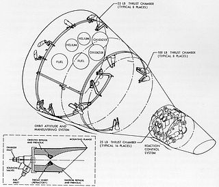
The Orbit Attitude and Maneuvering System (OAMS) was a reaction control system used in Earth orbit by the Project Gemini spacecraft. It provided both automatic and manual rotation and translation by means of 16 vernier thrusters using hypergolic propellants.
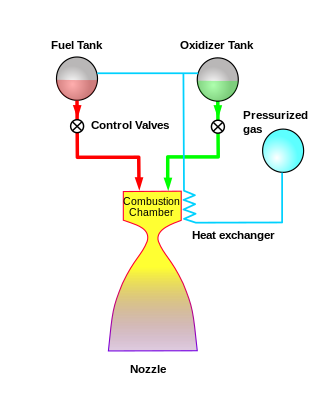
The pressure-fed engine is a class of rocket engine designs. A separate gas supply, usually helium, pressurizes the propellant tanks to force fuel and oxidizer to the combustion chamber. To maintain adequate flow, the tank pressures must exceed the combustion chamber pressure.

A reentry capsule is the portion of a space capsule which returns to Earth following a spaceflight. The shape is determined partly by aerodynamics; a capsule is aerodynamically stable falling blunt end first, which allows only the blunt end to require a heat shield for atmospheric entry. A crewed capsule contains the spacecraft's instrument panel, limited storage space, and seats for crew members. Because a capsule shape has little aerodynamic lift, the final descent is via parachute, either coming to rest on land, at sea, or by active capture by an aircraft. In contrast, the development of spaceplane reentry vehicles attempts to provide a more flexible reentry profile.
This is an alphabetical list of articles pertaining specifically to aerospace engineering. For a broad overview of engineering, see List of engineering topics. For biographies, see List of engineers.

A vernier thruster is a rocket engine used on a spacecraft for fine adjustments to the attitude or velocity of a spacecraft. Depending on the design of a craft's maneuvering and stability systems, it may simply be a smaller thruster complementing the main propulsion system, or it may complement larger attitude control thrusters, or may be a part of the reaction control system. The name is derived from vernier calipers which have a primary scale for gross measurements, and a secondary scale for fine measurements.

Lunar escape systems (LESS) were a series of emergency vehicles designed for never-flown long-duration Apollo missions. Because these missions were more hypothetical than the planned cancelled Apollo missions, the designs were never constructed. This concept was an outgrowth of the Lunar Flying Vehicle by Bell Aerospace.

The Space Shuttle orbiter is the spaceplane component of the Space Shuttle, a partially reusable orbital spacecraft system that was part of the discontinued Space Shuttle program. Operated from 1977 to 2011 by NASA, the U.S. space agency, this vehicle could carry astronauts and payloads into low Earth orbit, perform in-space operations, then re-enter the atmosphere and land as a glider, returning its crew and any on-board payload to the Earth.
The SpaceX Draco is a hypergolic liquid rocket engine designed and built by SpaceX for use in their space capsules. Two engine types have been built to date: Draco and SuperDraco.

The Orbital Maneuvering System (OMS) is a system of hypergolic liquid-propellant rocket engines used on the Space Shuttle and the Orion MPCV. Designed and manufactured in the United States by Aerojet, the system allowed the orbiter to perform various orbital maneuvers according to requirements of each mission profile: orbital injection after main engine cutoff, orbital corrections during flight, and the final deorbit burn for reentry. From STS-90 onwards the OMS were typically ignited part-way into the Shuttle's ascent for a few minutes to aid acceleration to orbital insertion. Notable exceptions were particularly high-altitude missions such as those supporting the Hubble Space Telescope (STS-31) or those with unusually heavy payloads such as Chandra (STS-93). An OMS dump burn also occurred on STS-51-F, as part of the Abort to Orbit procedure.
Spacecraft attitude control is the process of controlling the orientation of a spacecraft with respect to an inertial frame of reference or another entity such as the celestial sphere, certain fields, and nearby objects, etc.

The Soyuz MS is a revision of the Russian spacecraft series Soyuz first launched in 2016. It is an evolution of the Soyuz TMA-M spacecraft, with modernization mostly concentrated on the communications and navigation subsystems. It is used by Roscosmos for human spaceflight. The Soyuz MS has minimal external changes with respect to the Soyuz TMA-M, mostly limited to antennas and sensors, as well as the thruster placement.

The KTDU-80 (Russian: Корректирующе-Тормозная Двигательная Установка, КТДУ) is the latest of a family of integrated propulsion system that KB KhIMMASH has implemented for the Soyuz since the Soyuz-T. It integrates main propulsion, RCS and attitude control in a single system pressure fed from a common dual string redundant pressurized propellant system. The common propellant is UDMH and N2O4 and the main propulsion unit, is the S5.80 main engine. It generates 2.95 kN (660 lbf) of thrust with a chamber pressure of 880 kPa (128 psi) and a nozzle expansion of 153.8 that enables it to achieve a specific impulse of 302 s (2.96 km/s). It is rated for 30 starts with a total firing time of 890 seconds. The integrated system without the pressurization or tanks weighs 310 kg (680 lb); it is 1.2 m (47 in) long with a diameter of 2.1 m (83 in).


