Run-length limited or RLL coding is a line coding technique that is used to send arbitrary data over a communications channel with bandwidth limits. RLL codes are defined by four main parameters: m, n, d, k. The first two, m/n, refer to the rate of the code, while the remaining two specify the minimal d and maximal k number of zeroes between consecutive ones. This is used in both telecommunication and storage systems that move a medium past a fixed recording head.[1]
Specifically, RLL bounds the length of stretches (runs) of repeated bits during which the signal does not change. If the runs are too long, clock recovery is difficult; if they are too short, the high frequencies might be attenuated by the communications channel. By modulating the data, RLL reduces the timing uncertainty in decoding the stored data, which would lead to the possible erroneous insertion or removal of bits when reading the data back. This mechanism ensures that the boundaries between bits can always be accurately found (preventing bit slip), while efficiently using the media to reliably store the maximal amount of data in a given space.
Early disk drives used very simple encoding schemes, such as RLL (0,1) FM code, followed by RLL (1,3) MFM code, which were widely used in hard disk drives until the mid-1980s and are still used in digital optical discs such as CD, DVD, MD, Hi-MD and Blu-ray. Higher-density RLL (2,7) and RLL (1,7) codes became the defacto industry standard for hard disks by the early 1990s.
Need for RLL coding
On a hard disk drive, information is represented by changes in the direction of the magnetic field on the disk, and on magnetic media, the playback output is proportional to the density of flux transition. In a computer, information is represented by the voltage on a wire. No voltage on the wire in relation to a defined ground level would be a binary zero, and a positive voltage on the wire in relation to ground represents a binary one. Magnetic media, on the other hand, always carries a magnetic flux– either a "north" pole or a "south" pole. In order to convert the magnetic fields to binary data, some encoding method must be used to translate between the two.
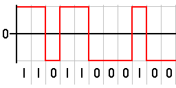
One of the simplest practical codes, modified non-return-to-zero-inverted (NRZI), simply encodes a 1 as a magnetic polarity transition, also known as a "flux reversal", and a zero as no transition. With the disk spinning at a constant rate, each bit is given an equal time period, a "data window", for the magnetic signal that represents that bit, and the flux reversal, if any, occurs at the start of this window. (Note: older hard disks used one fixed length of time as the data window over the whole disk, but modern disks are more complicated; for more on this, see zoned bit recording.)
This method is not quite that simple, as the playback output is proportional to the density of ones, a long run of zeros means no playback output at all.
In a simple example, consider the binary pattern 101 with a data window of 1ns (one nanosecond, or one billionth of a second). This will be stored on the disk as a change, followed by no change, and then another change. If the preceding magnetic polarity was already positive, the resulting pattern might look like this: −−+. A value of 255, or all binary ones, would be written as −+−+−+−+ or +−+−+−+−. A zero byte would be written as ++++++++ or −−−−−−−−. A 512-byte sector of zeros would be written as 4096 sequential bits with the same polarity.
Since a disk drive is a physical piece of hardware, the rotational speed of the drive can change slightly, due to a change in the motor speed or thermal expansion of the disk platter. The physical media on a floppy disk can also become deformed, causing larger timing errors, and the timing circuit on the controller itself may have small variations in speed. The problem is that, with a long string of zeros, there's no way for the disk drive's controller to know the exact position of the read head, and thus no way to know exactly how many zeros there are. A speed variation of even 0.1%, which is more precise than any practical floppy drive, could result in 4 bits being added to or removed from the 4096-bit data stream. Without some form of synchronization and error correction, the data would become completely unusable.
The other problem is due to the limits of magnetic media itself: it is only possible to write so many polarity changes in a certain amount of space, so there's an upper limit to how many ones can also be written sequentially, this depends on the linear velocity and the head gap.
To prevent this problem, data is coded in such a way that long repetitions of a single binary value do not occur. By limiting the number of zeros written consecutively to some maximum k, this makes it possible for the drive controller to stay synchronized. By limiting the number of zeros written in a row to some minimum d between each and every one, the overall frequency of polarity changes is reduced, allowing the drive to store more data in the same amount of space, resulting in either a smaller package for the same amount of data or more storage in the same size package.
All codes used to record on magnetic disks have limited the length of transition-free runs and can therefore be characterized as RLL codes. The earliest and simplest variants were given specific names, such as modified frequency modulation (MFM), and the name "RLL" is commonly used only for the more complex variants not given such specific names, but the term technically applies to them all.
The first "RLL" code used in hard drives was RLL (2,7), developed by IBM engineers and first used commercially in 1979 on the IBM 3370 DASD,[2][3][4] for use with the 4300 series mainframe. During the late 1980s, PC hard disks began using RLL proper (i.e. variants more complex than those that had received their own proper names, such as MFM). RLL codes have found almost universal application in optical-disc recording practice since 1980. In consumer electronics, RLLs like the EFM code (rate = 8/17, d = 2, k = 10) are employed in the Compact Disc (CD) and MiniDisc (MD), and the EFMPlus code (rate = 8/16, d = 2, k = 10) used in the DVD. Parameters d and k are the minimal and maximal allowed run lengths. For more coverage on the storage technologies, the references cited in this article are useful.[5][6]
Technical overview
Generally run length is the number of bits for which signal remains unchanged. A run length of 3 for bit 1, represents a sequence 111. For instance, the pattern of magnetic polarizations on the disk might be +−−−−++−−−++++++, with runs of length 1, 4, 2, 3, and 6. However, run-length limited coding terminology assumes NRZI encoding, so 1 bits indicate changes and 0 bits indicate the absence of change, the above sequence would be expressed as 11000101001000001, and only runs of zero bits are counted.
Somewhat confusingly, the run length is the number of zeros (0, 3, 1, 2 and 5 in the preceding) between adjacent ones, which is one less than the number of bit times the signal actually remains unchanged. Run-length limited sequences are characterized by two parameters, d and k, which stipulate the minimal and maximal zero-bit run length that can occur in the sequence. So RLL codes are generally specified as (d,k) RLL, e.g.: (1,3) RLL.
Coding
In the encoded format a "1" bit indicates a flux transition, while a "0" indicates that the magnetic field on the disk does not change for that time interval.
FM: (0,1) RLL
Generally, the term "RLL code" is used to refer to more elaborate encodings, but the original Frequency Modulation code, also called differential Manchester encoding, can be seen as a simple rate-1/2 RLL code. The added 1 bits are referred to as clock bits.
By extending the maximal run length to 2 adjacent 0 bits, the data rate can be improved to 4/5. This is the original IBM group coded recording variant
Data
Encoded
0000
11001
0001
11011
0010
10010
0011
10011
0100
11101
0101
10101
0110
10110
0111
10111
Data
Encoded
1000
11010
1001
01001
1010
01010
1011
01011
1100
11110
1101
01101
1110
01110
1111
01111
Where possible (11 out of 16 codes), the bit pattern abcd is encoded by prefixing it with the complement of a: aabcd. In the 5 cases where this would violate one of the rules (000d or ab00), a code beginning with 11 is substituted (11bea, where e = a ∨ d).
Note that to meet the definition of (0,2) RLL, it is not sufficient only that each 5-bit code contain no more than two consecutive zeros, but it is also necessary that any pair of 5-bit codes as a combined sequentially not contain more than two consecutive zeros. That is, there must not be more than two zeros between the last one bit in the first code and the first one bit in the second code, for any two arbitrarily chosen codes. This is required because for any RLL code, the run-length limits– 0 and 2 in this case– apply to the overall modulated bitstream, not just to the components of it that represent discrete sequences of plain data bits. (This rule must hold for any arbitrary pair of codes, without exception, because the input data may be any arbitrary sequence of bits.) The IBM GCR code above meets this condition, since the maximal run length of zeros at the beginning of any 5-bit code is one, and likewise the maximal run length at the end of any code is one, making a total run length of two at the junction between adjacent codes. (An example of the maximal run length occurring between codes can be seen in the example given above, where the code for the data "0010" ends with a zero and the code for the next data, "1101", begins with a zero, forming a run of two zeros at the junction of these two 5-bit codes.)
MFM: (1,3) RLL
Modified frequency modulation begins to get interesting, because its special properties allow its bits to be written to a magnetic medium with twice the density of an arbitrary bit stream. There is a limit to how close in time flux transitions can be for reading equipment to detect them, and that constrains how closely bits can be recorded on the medium: In the worst case, with an arbitrary bit stream, there are two consecutive ones, which produces two consecutive flux transitions in time, so bits must be spaced far enough apart that there would be sufficient time between those flux transitions for the reader to detect them. But this code imposes a constraint of d = 1, i.e. there is a minimum of one zero between each two ones. This means that in the worst case, flux transitions are two bit times apart, so the bits can be twice as close together as with the arbitrary bit stream without exceeding the reader's capabilities.
This doubled recording density compensates for the 1/2 coding rate of this code (it takes two bits to represent one bit of real information) and makes it equivalent to a rate-1 code.
The encoding is very similar to the FM encoding.
Data
Encoded
0
x0
1
01
Where "x" is the complement of the stream's previously encoded bit.
Except for the clock bits not always being one, this is the same as the FM table, and that is how this code gets its name. The inserted clock bits are 0 except between two 0 data bits.
When combined with the previous n-1 bit, the resulting encoding table for each data bit n effectively becomes.
(1,7) RLL maps 2 bits of data onto 3 bits on the disk, and the encoding is done in 2- or 4-bit groups. The encoding rules are: (x, y) becomes (NOT x, x AND y, NOT y), except (x, 0, 0, y) becomes (NOT x, x AND y, NOT y, 0, 0, 0).[7] When encoding according to the table below, the longest (last in the table) match must be used; those are exceptions handling situations where applying the earlier rules would lead to a violation of the code constraints.
(2,7) RLL is rate-1⁄2 code, mapping n bits of data onto 2n bits on the disk, like MFM, but because the minimal run length is 50% longer (3 bit times instead of 2), the bits can be written faster, achieving 50% higher effective data density. The encoding is done in 2-, 3- or 4-bit groups.
Western Digital WD5010A, WD5011A, WD50C12
Data
(2,7) RLL encoded
11
1000
10
0100
000
100100
010
000100
011
001000
0011
00001000
0010
00100100
Seagate ST11R, IBM
Data
(2,7) RLL encoded
11
1000
10
0100
000
000100
010
100100
011
001000
0011
00001000
0010
00100100
Perstor Systems ADRC
Data
(2,7) RLL encoded
11
1000
10
0100
000
100100
010
000100
001
001000
0111
00001000
0110
00100100
The encoded forms begin with at most 4, and end with at most 3 zero bits, giving the maximal run length of 7.
The HHH(1,13) code is a rate-2/3 code developed by three IBM researchers (Hirt, Hassner, and Heise) for use in the 16MB/s IrDA VFIR physical layer.[8] Unlike magnetic encoding, this is designed for an infrared transmitter, where a 0 bit represents "off" and a 1 bit represents "on". Because 1 bits consume more power to transmit, this is designed to limit the density of 1 bits to less than 50%. In particular, it is a (1,13|5) RLL code, where the final 5 indicates the additional constraint that there are at most 5 consecutive "10" bit pairs.
Data
Encoded
00
010
01
001
10
100
11
101
01 10
001 000
01 11
010 000
11 10
101 000
11 11
100 000
00 11 00
010 000 000
00 11 01
001 000 000
10 11 00
100 000 000
10 11 01
101 000 000
00 11 10 11
010 000 000 000
10 11 10 11
100 000 000 000
The first eight rows describe a standard (1,7)-RLL code. The additional six exceptions increase the maximal run of zeros to 13 (in the legal pattern 100000000000001, which represents 10 11 10 11, followed by 01), but limit the maximal average ones density to 1⁄3. The longest run of 1–0 pairs is 000101010101000.
This code limits the ones density to between 1⁄12 and 1⁄3, with an average of 25.8%.
Examples
For example, let us encode the bit sequence 10110010 with different encodings
Encoding
Data
Encoded
RLL(0,1)
10110010
1110111110101110
RLL(0,2)
1011 0010
01011 10010
RLL(1,3)
10110010
0100010100100100
RLL(1,7)
10 11 00 10
001 010 101 001
RLL(2,7)
10 11 0010
0100 1000 00100100
Densities
Suppose a magnetic tape can contain up to 3200 flux reversals per inch. A modified frequency modulation, or (1,3) RLL encoding, stores each data bit as two bits on tape, but since there is guaranteed to be one 0 (no flux reversal) bit between any 1 (flux reversal) bits, then it is possible to store 6400 encoded bits per inch on the tape, or 3200 data bits per inch. A (1,7) RLL encoding can also store 6400 encoded bits per inch on the tape, but since it only takes 3 encoded bits to store 2 data bits, this is 4267 data bits per inch. A (2,7) RLL encoding takes 2 encoded bits to store each data bit, but since there is guaranteed to be two 0 bits between any 1 bits, then it is possible to store 9600 encoded bits per inch on the tape, or 4800 data bits per inch.
The flux-reversal densities on hard drives are significantly greater, but the same improvements in storage density are seen by using different encoding systems.
The Commodore 1571 is Commodore's high-end 5¼" floppy disk drive, announced in the summer of 1985. With its double-sided drive mechanism, it has the ability to use double-sided, double-density (DS/DD) floppy disks, storing a total of 360 kB per floppy. It also implemented a "burst mode" that improved transfer speeds, helping address the very slow performance of previous Commodore drives.
A hard disk drive (HDD), hard disk, hard drive, or fixed disk, is an electro-mechanical data storage device that stores and retrieves digital data using magnetic storage with one or more rigid rapidly rotating platters coated with magnetic material. The platters are paired with magnetic heads, usually arranged on a moving actuator arm, which read and write data to the platter surfaces. Data is accessed in a random-access manner, meaning that individual blocks of data can be stored and retrieved in any order. HDDs are a type of non-volatile storage, retaining stored data when powered off. Modern HDDs are typically in the form of a small rectangular box.
Differential Manchester encoding (DM) is a line code in digital frequency modulation in which data and clock signals are combined to form a single two-level self-synchronizing data stream. Each data bit is encoded by a presence or absence of signal level transition in the middle of the bit period, followed by the mandatory level transition at the beginning. The code is insensitive to an inversion of polarity. In various specific applications, this method is also called by various other names, including biphase mark code (CC), F2F, Aiken biphase, and conditioned diphase.
In telecommunication, a line code is a pattern of voltage, current, or photons used to represent digital data transmitted down a communication channel or written to a storage medium. This repertoire of signals is usually called a constrained code in data storage systems. Some signals are more prone to error than others as the physics of the communication channel or storage medium constrains the repertoire of signals that can be used reliably.
In telecommunication, a non-return-to-zero (NRZ) line code is a binary code in which ones are represented by one significant condition, usually a positive voltage, while zeros are represented by some other significant condition, usually a negative voltage, with no other neutral or rest condition.
The ST-506 and ST-412 were early hard disk drive products introduced by Seagate in 1980 and 1981 respectively, that later became construed as hard disk drive interfaces: the ST-506 disk interface and the ST-412 disk interface. Compared to the ST-506 precursor, the ST-412 implemented a refinement to the seek speed, and increased the drive capacity from 5 MB to 10 MB, but was otherwise highly similar.
In computer science, group coded recording or group code recording (GCR) refers to several distinct but related encoding methods for representing data on magnetic media. The first, used in 6250 bpi magnetic tape since 1973, is an error-correcting code combined with a run-length limited (RLL) encoding scheme, belonging into the group of modulation codes. The others are different mainframe hard disk as well as floppy disk encoding methods used in some microcomputers until the late 1980s. GCR is a modified form of a NRZI code, but necessarily with a higher transition density.
Modified frequency modulation (MFM) is a run-length limited (RLL) line code used to encode data on most floppy disks and some hard disk drives. It was first introduced on hard disks in 1970 with the IBM 3330 and then in floppy disk drives beginning with the IBM 53FD in 1976.
In computer data storage, partial-response maximum-likelihood (PRML) is a method for recovering the digital data from the weak analog read-back signal picked up by the head of a magnetic disk drive or tape drive. PRML was introduced to recover data more reliably or at a greater areal-density than earlier simpler schemes such as peak-detection. These advances are important because most of the digital data in the world is stored using magnetic storage on hard disk or tape drives.
In telecommunications, 8b/10b is a line code that maps 8-bit words to 10-bit symbols to achieve DC balance and bounded disparity, and at the same time provide enough state changes to allow reasonable clock recovery. This means that the difference between the counts of ones and zeros in a string of at least 20 bits is no more than two, and that there are not more than five ones or zeros in a row. This helps to reduce the demand for the lower bandwidth limit of the channel necessary to transfer the signal.
Eight-to-fourteen modulation (EFM) is a data encoding technique – formally, a line code – used by compact discs (CD), laserdiscs (LD) and pre-Hi-MD MiniDiscs. EFMPlus is a related code, used in DVDs and Super Audio CDs (SACDs).
In telecommunication, 4B5B is a form of data communications line code. 4B5B maps groups of 4 bits of data onto groups of 5 bits for transmission. These 5-bit words are pre-determined in a dictionary and they are chosen to ensure that there will be sufficient transitions in the line state to produce a self-clocking signal. A collateral effect of the code is that 25% more bits are needed to send the same information.
9-track tape is a format for magnetic-tape data storage, introduced with the IBM System/360 in 1964. The 1⁄2 inch (12.7 mm) wide magnetic tape media and reels have the same size as the earlier IBM 7-track format it replaced, but the new format has eight data tracks and one parity track for a total of nine parallel tracks. Data is stored as 8-bit characters, spanning the full width of the tape. Various recording methods have been employed during its lifetime as tape speed and data density increased, including PE, GCR, and NRZI. Tapes come in various sizes up to 3,600 feet (1,100 m) in length.
Magnetic-tape data storage is a system for storing digital information on magnetic tape using digital recording.
In computer disk storage, a sector is a subdivision of a track on a magnetic disk or optical disc. For most disks, each sector stores a fixed amount of user-accessible data, traditionally 512 bytes for hard disk drives (HDDs) and 2048 bytes for CD-ROMs and DVD-ROMs. Newer HDDs and SSDs use 4096-byte (4 KiB) sectors, which are known as the Advanced Format (AF).
Peter A. Franaszek is an American information theorist, an IEEE Fellow, a research staff member emeritus at the IBM T.J. Watson Research Center and a former member of the IBM Academy of Technology. He received his Sc.B. from Brown University in 1962, and his Ph.D. from Princeton University in 1966.
Noise-Predictive Maximum-Likelihood (NPML) is a class of digital signal-processing methods suitable for magnetic data storage systems that operate at high linear recording densities. It is used for retrieval of data recorded on magnetic media.
Hard disk drives are accessed over one of a number of bus types, including parallel ATA, Serial ATA (SATA), SCSI, Serial Attached SCSI (SAS), and Fibre Channel. Bridge circuitry is sometimes used to connect hard disk drives to buses with which they cannot communicate natively, such as IEEE 1394, USB, SCSI, NVMe and Thunderbolt.
RL01 and RL02 drives are moving head magnetic disk drives manufactured by Digital Equipment Corporation for the PDP-8 and PDP-11 microcomputers. The RL01 and RL02 drives stored approximate 5MB and 10MB respectively, utilizing a removable data cartridge. The drives are typically mounted in a standard 19" rack and weigh 34 kg. Up to four RL02 or RL01 drives may be used, in any combination, from a single controller. Typically an RL11 in the case of a Unibus PDP-11 and an RLV11 or RLV12 in the case of a Q-bus PDP-11. On the PDP-8/a the controller is an RL8A which consists of an M8433 Hex wide Omnibus card.
Frequency modulation encoding, or simply FM, is a method of storing data that saw widespread use in early floppy disk drives and hard disk drives. The data is modified using differential Manchester encoding when written to allow clock recovery to address timing effects known as "jitter" seen on disk media. It was introduced on IBM mainframe drives and was almost universal among early minicomputer and microcomputer floppies. In the case of floppies, FM encoding allowed about 80 kB of data to be stored on a 5+1⁄4-inch disk.
References
↑ Kees Schouhamer Immink (October 2022). "Innovation in Constrained Codes". IEEE Communications Magazine. 60 (10): 20–24. doi:10.1109/MCOM.002.2200249. A constrained system is defined by a constrained set of 'good' or 'allowable' sequences to be recorded or transmitted. Constrained coding focuses on the analysis of constrained systems and the design of efficient encoders and decoders that transform arbitrary user sequences into constrained sequences.
This page is based on this Wikipedia article Text is available under the CC BY-SA 4.0 license; additional terms may apply. Images, videos and audio are available under their respective licenses.