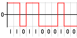
In telecommunication, a non-return-to-zero (NRZ) line code is a binary code in which ones are represented by one significant condition, usually a positive voltage, while zeros are represented by some other significant condition, usually a negative voltage, with no other neutral or rest condition.
Data communication or digital communications, including data transmission and data reception, is the transfer and reception of data in the form of a digital bitstream or a digitized analog signal transmitted over a point-to-point or point-to-multipoint communication channel. Examples of such channels are copper wires, optical fibers, wireless communication using radio spectrum, storage media and computer buses. The data are represented as an electromagnetic signal, such as an electrical voltage, radiowave, microwave, or infrared signal.

A Universal Asynchronous Receiver-Transmitter is a protocol for asynchronous serial communication in which the data format and transmission speeds are configurable. It sends data bits one by one, from the least significant to the most significant, framed by start and stop bits so that precise timing is handled by the communication channel. The electric signaling levels are handled by a driver circuit external to the UART. Common signal levels are RS-232, RS-485, and raw TTL for short debugging links. Early teletypewriters used current loops.
High-Level Data Link Control (HDLC) is a bit-oriented code-transparent synchronous data link layer protocol developed by the International Organization for Standardization (ISO). The standard for HDLC is ISO/IEC 13239:2002.

I2C (Inter-Integrated Circuit; pronounced as “eye-squared-C”), alternatively known as I2C or IIC, is a synchronous, multi-master/multi-slave (controller/target), single-ended, serial communication bus invented in 1982 by Philips Semiconductors. It is widely used for attaching lower-speed peripheral ICs to processors and microcontrollers in short-distance, intra-board communication.
A controller area network is a vehicle bus standard designed to allow microcontrollers and devices to communicate with each other. It is a message-based protocol, designed originally for multiplex electrical wiring within automobiles to save on copper, but it can also be used in many other contexts. For each device, the data in a frame is transmitted serially but in such a way that if more than one device transmits at the same time, the highest priority device can continue while the others back off. Frames are received by all devices, including by the transmitting device.
Serial Peripheral Interface (SPI) is a de facto standard for synchronous serial communication, used primarily in embedded systems for short-distance wired communication between integrated circuits.

1-Wire is a wired half-duplex serial bus designed by Dallas Semiconductor that provides low-speed (16.3 kbit/s) data communication and supply voltage over a single conductor.
Modbus or MODBUS is a client/server data communications protocol in the application layer of the OSI model. It was originally published by Modicon in 1979 for use with its programmable logic controllers (PLCs). Modbus has become a de facto standard communication protocol for communication between industrial electronic devices in a wide range of buses and network.
LIN is a serial network protocol used for communication between components in vehicles. It is a single wire, serial network protocol that supports communications up to 19.2 Kbit/s at a bus length of 40 meters. The need for a cheap serial network arose as the technologies and the facilities implemented in the car grew, while the CAN bus was too expensive to implement for every component in the car. European car manufacturers started using different serial communication technologies, which led to compatibility problems.
Synchronous and asynchronous transmissions are two different methods of transmission synchronization. Synchronous transmissions are synchronized by an external clock, while asynchronous transmissions are synchronized by special signals along the transmission medium.

On-board diagnostics (OBD) is a term referring to a vehicle's self-diagnostic and reporting capability. In the United States, this self-diagnostic is a requirement to comply with Federal Emissions standards to detect failures that may increase the vehicle tailpipe emissions to more than 150% of the standard to which it was originally certified.
ARINC 429, the "Mark 33 Digital Information Transfer System (DITS)," is the ARINC technical standard for the predominant avionics data bus used on most higher-end commercial and transport aircraft. It defines the physical and electrical interfaces of a two-wire data bus and a data protocol to support an aircraft's avionics local area network.

IEEE Standard 1355-1995, IEC 14575, or ISO 14575 is a data communications standard for Heterogeneous Interconnect (HIC).
SDI-12 is an asynchronous serial communications protocol for intelligent sensors that monitor environment data. These instruments are typically low-power, are used at remote locations, and usually communicate with a data logger or other data acquisition device. The protocol follows a client-server configuration whereby a data logger requests data from the intelligent sensors, each identified with a unique address.
The Serial Low-power Inter-chip Media Bus (SLIMbus) is a standard interface between baseband or application processors and peripheral components in mobile terminals. It was developed within the MIPI Alliance, founded by ARM, Nokia, STMicroelectronics and Texas Instruments. The interface supports many digital audio components simultaneously, and carries multiple digital audio data streams at differing sample rates and bit widths.
ARINC 818: Avionics Digital Video Bus (ADVB) is a video interface and protocol standard developed for high bandwidth, low-latency, uncompressed digital video transmission in avionics systems. The standard, which was released in January 2007, has been advanced by ARINC and the aerospace community to meet the stringent needs of high performance digital video. The specification was updated and ARINC 818-2 was released in December 2013, adding a number of new features, including link rates up to 32X fibre channel rates, channel-bonding, switching, field sequential color, bi-directional control and data-only links.
Synchronous Serial Interface (SSI) is a widely used serial interface standard for industrial applications between a master (e.g. controller) and a slave (e.g. sensor). SSI is based on RS-422 standards and has a high protocol efficiency in addition to its implementation over various hardware platforms, making it very popular among sensor manufacturers. SSI was originally developed by Max Stegmann GmbH in 1984 for transmitting the position data of absolute encoders – for this reason, some servo/drive equipment manufacturers refer to their SSI port as a "Stegmann Interface". It was formerly covered by the German patent DE 34 45 617 which expired in 1990. It is very suitable for applications demanding reliability and robustness in measurements under varying industrial environments.

I3C is a specification to enable communication between computer chips by defining the electrical connection between the chips and signaling patterns to be used. Short for "Improved Inter Integrated Circuit", the standard defines the electrical connection between the chips to be a two wire, shared (multidrop), serial data bus, one wire (SCL) being used as a clock to define the sampling times, the other wire (SDA) being used as a data line whose voltage can be sampled. The standard defines a signalling protocol in which multiple chips can control communication and thereby act as the bus controller.
CAN FD is a data-communication protocol used for broadcasting sensor data and control information on 2 wire interconnections between different parts of electronic instrumentation and control system. This protocol is used in modern high performance vehicles.
