Scene graph

Last updated
Architecture of OpenSceneGraph, an open-source 3D graphics API supporting feature-rich and widely adopted scene graph implementation. Architecture of OpenSceneGraph.jpg
Architecture of OpenSceneGraph, an open-source 3D graphics API supporting feature-rich and widely adopted scene graph implementation.

A scene graph is a general data structure commonly used by vector-based graphics editing applications and modern computer games, which arranges the logical and often spatial representation of a graphical scene. It is a collection of nodes in a graph or tree structure. A tree node may have many children but only a single parent, with the effect of a parent applied to all its child nodes; an operation performed on a group automatically propagates its effect to all of its members. In many programs, associating a geometrical transformation matrix (see also transformation and matrix) at each group level and concatenating such matrices together is an efficient and natural way to process such operations. A common feature, for instance, is the ability to group related shapes and objects into a compound object that can then be manipulated as easily as a single object.

Contents

Scene graphs in graphics editing tools

In vector-based graphics editing, each leaf node in a scene graph represents some atomic unit of the document, usually a shape such as an ellipse or Bezier path. Although shapes themselves (particularly paths) can be decomposed further into nodes such as spline nodes, it is practical to think of the scene graph as composed of shapes rather than going to a lower level of representation.

Another useful and user-driven node concept is the layer. A layer acts like a transparent sheet upon which any number of shapes and shape groups can be placed. The document then becomes a set of layers, any of which can be conveniently made invisible, dimmed, or locked (made read-only). Some applications place all layers in a linear list, while others support layers within layers to any desired depth.

Internally, there may be no real structural difference between layers and groups at all, since they are both just nodes of a scene graph. If differences are needed, a common type declaration in C++ would be to make a generic node class, and then derive layers and groups as subclasses. A visibility member, for example, would be a feature of a layer, but not necessarily of a group.

Scene graphs in games and 3D applications

Scene graphs are useful for modern games using 3D graphics and increasingly large worlds or levels. In such applications, nodes in a scene graph (generally) represent entities or objects in the scene.

For instance, a game might define a logical relationship between a knight and a horse so that the knight is considered an extension to the horse. The scene graph would have a 'horse' node with a 'knight' node attached to it.

The scene graph may also describe the spatial, as well as the logical, relationship of the various entities: the knight moves through 3D space as the horse moves.

In these large applications, memory requirements are major considerations when designing a scene graph. For this reason, many large scene graph systems use geometry instancing to reduce memory costs and increase speed. In our example above, each knight is a separate scene node, but the graphical representation of the knight (made up of a 3D mesh, textures, materials and shaders) is instanced. This means that only a single copy of the data is kept, which is then referenced by any 'knight' nodes in the scene graph. This allows a reduced memory budget and increased speed, since when a new knight node is created, the appearance data needs not be duplicated.

Scene graph implementation

The simplest form of scene graph uses an array or linked list data structure, and displaying its shapes is simply a matter of linearly iterating the nodes one by one. Other common operations, such as checking to see which shape intersects the mouse pointer are also done via linear searches. For small scene graphs, this tends to suffice.

Scene graph operations and dispatch

Applying an operation on a scene graph requires some way of dispatching an operation based on a node's type. For example, in a render operation, a transformation group node would accumulate its transformation by matrix multiplication, vector displacement, quaternions or Euler angles. After which a leaf node sends the object off for rendering to the renderer. Some implementations might render the object directly, which invokes the underlying rendering API, such as DirectX or OpenGL. But since the underlying implementation of the rendering API usually lacks portability, one might separate the scene graph and rendering systems instead. In order to accomplish this type of dispatching, several different approaches can be taken.

In object-oriented languages such as C++, this can easily be achieved by virtual functions, where each represents an operation that can be performed on a node. Virtual functions are simple to write, but it is usually impossible to add new operations to nodes without access to the source code. Alternatively, the visitor pattern can be used. This has a similar disadvantage in that it is similarly difficult to add new node types.

Other techniques involve the use of RTTI (Run-Time Type Information). The operation can be realised as a class that is passed to the current node; it then queries the node's type using RTTI and looks up the correct operation in an array of callbacks or functors. This requires that the map of types to callbacks or functors be initialized at runtime, but offers more flexibility, speed and extensibility.

Variations on these techniques exist, and new methods can offer added benefits. One alternative is scene graph rebuilding, where the scene graph is rebuilt for each of the operations performed. This, however, can be very slow, but produces a highly optimised scene graph. It demonstrates that a good scene graph implementation depends heavily on the application in which it is used.

Traversals

Traversals are the key to the power of applying operations to scene graphs. A traversal generally consists of starting at some arbitrary node (often the root of the scene graph), applying the operation(s) (often the updating and rendering operations are applied one after the other), and recursively moving down the scene graph (tree) to the child nodes, until a leaf node is reached. At this point, many scene graph engines then traverse back up the tree, applying a similar operation. For example, consider a render operation that takes transformations into account: while recursively traversing down the scene graph hierarchy, a pre-render operation is called. If the node is a transformation node, it adds its own transformation to the current transformation matrix. Once the operation finishes traversing all the children of a node, it calls the node's post-render operation so that the transformation node can undo the transformation. This approach drastically reduces the necessary amount of matrix multiplication.[ citation needed ]

Some scene graph operations are actually more efficient when nodes are traversed in a different order – this is where some systems implement scene graph rebuilding to reorder the scene graph into an easier-to-parse format or tree.

For example, in 2D cases, scene graphs typically render themselves by starting at the tree's root node and then recursively draw the child nodes. The tree's leaves represent the most foreground objects. Since drawing proceeds from back to front with closer objects simply overwriting farther ones, the process is known as employing the Painter's algorithm. In 3D systems, which often employ depth buffers, it is more efficient to draw the closest objects first, since farther objects often need only be depth-tested instead of actually rendered, because they are occluded by nearer objects.

Scene graphs and bounding volume hierarchies (BVHs)

Bounding Volume Hierarchies (BVHs) are useful for numerous tasks – including efficient culling and speeding up collision detection between objects. A BVH is a spatial structure, but doesn't have to partition the geometry (see spatial partitioning below).

A BVH is a tree of bounding volumes (often spheres, axis-aligned bounding boxes or oriented bounding boxes). At the bottom of the hierarchy, the size of the volume is just large enough to encompass a single object tightly (or possibly even some smaller fraction of an object in high resolution BVHs). As one ascends the hierarchy, each node has its own volume that tightly encompasses all the volumes beneath it. At the root of the tree is a volume that encompasses all the volumes in the tree (the whole scene).

BVHs are useful for speeding up collision detection between objects. If an object's bounding volume does not intersect a volume higher in the tree, it cannot intersect any object below that node (so they are all rejected very quickly).

There are some similarities between BVHs and scene graphs. A scene graph can easily be adapted to include/become a BVH – if each node has a volume associated or there is a purpose-built "bound node" added in at convenient location in the hierarchy. This may not be the typical view of a scene graph, but there are benefits to including a BVH in a scene graph.

Scene graphs and spatial partitioning

An effective way of combining spatial partitioning and scene graphs is by creating a scene leaf node that contains the spatial partitioning data.[ clarification needed ] This can increase computational efficiency of rendering.

Spatial data is usually static and generally contains non-moving scene data in some partitioned form.[ clarification needed ] Some systems may have the systems and their rendering separately. This is fine and there are no real advantages to either method. In particular, it is bad to have the scene graph contained within the spatial partitioning system, as the scene graph is better thought of as the grander system to the spatial partitioning.[ neutrality is disputed ]

Very large drawings, or scene graphs that are generated solely at runtime (as happens in ray tracing rendering programs), require defining of group nodes in a more automated fashion. A raytracer, for example, will take a scene description of a 3D model and build an internal representation that breaks up its individual parts into bounding boxes (also called bounding slabs). These boxes are grouped hierarchically so that ray intersection tests (as part of visibility determination) can be efficiently computed. A group box that does not intersect an eye ray, for example, can entirely skip testing any of its members.

A similar efficiency holds in 2D applications as well. If the user has magnified a document so that only part of it is visible on his computer screen, and then scrolls in it, it is useful to use a bounding box (or in this case, a bounding rectangle scheme) to quickly determine which scene graph elements are visible and thus actually need to be drawn.

Depending on the particulars of the application's drawing performance, a large part of the scene graph's design can be impacted by rendering efficiency considerations. In 3D video games such as Quake, binary space partitioning (BSP) trees are heavily favored to minimize visibility tests. BSP trees, however, take a very long time to compute from design scene graphs, and must be recomputed if the design scene graph changes, so the levels tend to remain static, and dynamic characters aren't generally considered in the spatial partitioning scheme.

Scene graphs for dense regular objects such as heightfields and polygon meshes tend to employ quadtrees and octrees, which are specialized variants of a 3D bounding box hierarchy. Since a heightfield occupies a box volume itself, recursively subdividing this box into eight subboxes (hence the 'oct' in octree) until individual heightfield elements are reached is efficient and natural. A quadtree is simply a 2D octree.

Standards

PHIGS

PHIGS was the first commercial scene graph specification, and became an ANSI standard in 1988. Disparate implementations were provided by Unix hardware vendors. The HOOPS 3D Graphics System appears to have been the first commercial scene graph library provided by a single software vendor. It was designed to run on disparate lower-level 2D and 3D interfaces, with the first major production version (v3.0) completed in 1991.

SGI

Silicon Graphics (SGI) released OpenGL Performer or more commonly called Performer in 1991 which was the primary scenegraph system for most SGI products into the future. IRIS Inventor 1.0 (1992) was released by SGI, which was a high level scene graph built on top of Performer. It was followed up with Open Inventor in 1994, another iteration of the high level scene graph built on top of newer releases of Performer. More 3D scene graph libraries can be found in Category:3D scenegraph APIs.

X3D

X3D is a royalty-free open standards file format and run-time architecture to represent and communicate 3D scenes and objects using XML. It is an ISO-ratified standard that provides a system for the storage, retrieval and playback of real-time graphics content embedded in applications, all within an open architecture to support a wide array of domains and user scenarios.

See also

Related Research Articles

<span class="mw-page-title-main">Binary space partitioning</span> Method for recursively subdividing a space into two subsets using hyperplanes

In computer science, binary space partitioning (BSP) is a method for space partitioning which recursively subdivides a Euclidean space into two convex sets by using hyperplanes as partitions. This process of subdividing gives rise to a representation of objects within the space in the form of a tree data structure known as a BSP tree.

Autodesk 3ds Max, formerly 3D Studio and 3D Studio Max, is a professional 3D computer graphics program for making 3D animations, models, games and images. It is developed and produced by Autodesk Media and Entertainment. It has modeling capabilities and a flexible plugin architecture and must be used on the Microsoft Windows platform. It is frequently used by video game developers, many TV commercial studios, and architectural visualization studios. It is also used for movie effects and movie pre-visualization. 3ds Max features shaders, dynamic simulation, particle systems, radiosity, normal map creation and rendering, global illumination, a customizable user interface, and its own scripting language.

<span class="mw-page-title-main">Ray casting</span> Methodological basis for 3D CAD/CAM solid modeling and image rendering

Ray casting is the methodological basis for 3D CAD/CAM solid modeling and image rendering. It is essentially the same as ray tracing for computer graphics where virtual light rays are "cast" or "traced" on their path from the focal point of a camera through each pixel in the camera sensor to determine what is visible along the ray in the 3D scene. The term "Ray Casting" was introduced by Scott Roth while at the General Motors Research Labs from 1978–1980. His paper, "Ray Casting for Modeling Solids", describes modeled solid objects by combining primitive solids, such as blocks and cylinders, using the set operators union (+), intersection (&), and difference (-). The general idea of using these binary operators for solid modeling is largely due to Voelcker and Requicha's geometric modelling group at the University of Rochester. See solid modeling for a broad overview of solid modeling methods. This figure on the right shows a U-Joint modeled from cylinders and blocks in a binary tree using Roth's ray casting system in 1979.

<span class="mw-page-title-main">Hidden-surface determination</span> Visibility in 3D computer graphics

In 3D computer graphics, hidden-surface determination is the process of identifying what surfaces and parts of surfaces can be seen from a particular viewing angle. A hidden-surface determination algorithm is a solution to the visibility problem, which was one of the first major problems in the field of 3D computer graphics. The process of hidden-surface determination is sometimes called hiding, and such an algorithm is sometimes called a hider. When referring to line rendering it is known as hidden-line removal. Hidden-surface determination is necessary to render a scene correctly, so that one may not view features hidden behind the model itself, allowing only the naturally viewable portion of the graphic to be visible.

DOT is a graph description language, developed as a part of the Graphviz project. DOT graphs are typically stored as files with the .gv or .dot filename extension — .gv is preferred, to avoid confusion with the .dot extension used by versions of Microsoft Word before 2007. dot is also the name of the main program to process DOT files in the Graphviz package.

<span class="mw-page-title-main">Quadtree</span> Tree data structure in which each internal node has exactly four children, to partition a 2D area

A quadtree is a tree data structure in which each internal node has exactly four children. Quadtrees are the two-dimensional analog of octrees and are most often used to partition a two-dimensional space by recursively subdividing it into four quadrants or regions. The data associated with a leaf cell varies by application, but the leaf cell represents a "unit of interesting spatial information".

<span class="mw-page-title-main">Bounding volume</span> Closed volume that completely contains the union of a set of objects

In computer graphics and computational geometry, a bounding volume for a set of objects is a closed volume that completely contains the union of the objects in the set. Bounding volumes are used to improve the efficiency of geometrical operations by using simple volumes to contain more complex objects. Normally, simpler volumes have simpler ways to test for overlap.

<span class="mw-page-title-main">Octree</span> Tree data structure in which each internal node has exactly eight children, to partition a 3D space

An octree is a tree data structure in which each internal node has exactly eight children. Octrees are most often used to partition a three-dimensional space by recursively subdividing it into eight octants. Octrees are the three-dimensional analog of quadtrees. The word is derived from oct + tree. Octrees are often used in 3D graphics and 3D game engines.

<span class="mw-page-title-main">R-tree</span> Data structures used in spatial indexing

R-trees are tree data structures used for spatial access methods, i.e., for indexing multi-dimensional information such as geographical coordinates, rectangles or polygons. The R-tree was proposed by Antonin Guttman in 1984 and has found significant use in both theoretical and applied contexts. A common real-world usage for an R-tree might be to store spatial objects such as restaurant locations or the polygons that typical maps are made of: streets, buildings, outlines of lakes, coastlines, etc. and then find answers quickly to queries such as "Find all museums within 2 km of my current location", "retrieve all road segments within 2 km of my location" or "find the nearest gas station". The R-tree can also accelerate nearest neighbor search for various distance metrics, including great-circle distance.

In computer graphics, level of detail (LOD) refers to the complexity of a 3D model representation. LOD can be decreased as the model moves away from the viewer or according to other metrics such as object importance, viewpoint-relative speed or position. LOD techniques increase the efficiency of rendering by decreasing the workload on graphics pipeline stages, usually vertex transformations. The reduced visual quality of the model is often unnoticed because of the small effect on object appearance when distant or moving fast.

<span class="mw-page-title-main">Real-time computer graphics</span> Sub-field of computer graphics

Real-time computer graphics or real-time rendering is the sub-field of computer graphics focused on producing and analyzing images in real time. The term can refer to anything from rendering an application's graphical user interface (GUI) to real-time image analysis, but is most often used in reference to interactive 3D computer graphics, typically using a graphics processing unit (GPU). One example of this concept is a video game that rapidly renders changing 3D environments to produce an illusion of motion.

<span class="mw-page-title-main">Z-order curve</span> Mapping function that preserves data point locality

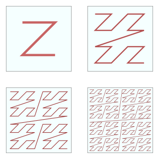
In mathematical analysis and computer science, functions which are Z-order, Lebesgue curve, Morton space-filling curve, Morton order or Morton code map multidimensional data to one dimension while preserving locality of the data points. It is named in France after Henri Lebesgue, who studied it in 1904, and named in the United States after Guy Macdonald Morton, who first applied the order to file sequencing in 1966. The z-value of a point in multidimensions is simply calculated by interleaving the binary representations of its coordinate values. Once the data are sorted into this ordering, any one-dimensional data structure can be used, such as simple one dimensional arrays, binary search trees, B-trees, skip lists or hash tables. The resulting ordering can equivalently be described as the order one would get from a depth-first traversal of a quadtree or octree.

<span class="mw-page-title-main">Autodesk Softimage</span> Discontinued 3D graphics software

Autodesk Softimage, or simply Softimage was a 3D computer graphics application, for producing 3D computer graphics, 3D modeling, and computer animation. Now owned by Autodesk and formerly titled Softimage|XSI, the software has been predominantly used in the film, video game, and advertising industries for creating computer generated characters, objects, and environments.

A bounding volume hierarchy (BVH) is a tree structure on a set of geometric objects. All geometric objects, which form the leaf nodes of the tree, are wrapped in bounding volumes. These nodes are then grouped as small sets and enclosed within larger bounding volumes. These, in turn, are also grouped and enclosed within other larger bounding volumes in a recursive fashion, eventually resulting in a tree structure with a single bounding volume at the top of the tree. Bounding volume hierarchies are used to support several operations on sets of geometric objects efficiently, such as in collision detection and ray tracing.

A spatial database is a general-purpose database that has been enhanced to include spatial data that represents objects defined in a geometric space, along with tools for querying and analyzing such data. Most spatial databases allow the representation of simple geometric objects such as points, lines and polygons. Some spatial databases handle more complex structures such as 3D objects, topological coverages, linear networks, and triangulated irregular networks (TINs). While typical databases have developed to manage various numeric and character types of data, such databases require additional functionality to process spatial data types efficiently, and developers have often added geometry or feature data types. The Open Geospatial Consortium (OGC) developed the Simple Features specification and sets standards for adding spatial functionality to database systems. The SQL/MM Spatial ISO/IEC standard is a part of the SQL/MM multimedia standard and extends the Simple Features standard with data types that support circular interpolations. Almost all current relational and object-relational database management systems now have spatial extensions, and some GIS software vendors have developed their own spatial extensions to database management systems.

A bounding interval hierarchy (BIH) is a partitioning data structure similar to that of bounding volume hierarchies or kd-trees. Bounding interval hierarchies can be used in high performance ray tracing and may be especially useful for dynamic scenes.

Visualization Library (VL) is an open source C++ middleware for 2D/3D graphics applications based on OpenGL 4, designed to develop portable applications for the Microsoft Windows, Linux and Mac OS X operating systems.

<span class="mw-page-title-main">GTK Scene Graph Kit</span>

GTK Scene Graph Kit (GSK) is the rendering and scene graph API for GTK introduced with version 3.90. GSK lies between the graphical control elements (widgets) and the rendering.

This is a glossary of terms relating to computer graphics.

Caustic Graphics was a computer graphics and fabless semiconductor company that developed technologies to bring real-time ray-traced computer graphics to the mass market.

References

Books

Articles