An electrical network is an interconnection of electrical components or a model of such an interconnection, consisting of electrical elements. An electrical circuit is a network consisting of a closed loop, giving a return path for the current. Linear electrical networks, a special type consisting only of sources, linear lumped elements, and linear distributed elements, have the property that signals are linearly superimposable. They are thus more easily analyzed, using powerful frequency domain methods such as Laplace transforms, to determine DC response, AC response, and transient response.
Electronic design automation (EDA), also referred to as electronic computer-aided design (ECAD), is a category of software tools for designing electronic systems such as integrated circuits and printed circuit boards. The tools work together in a design flow that chip designers use to design and analyze entire semiconductor chips. Since a modern semiconductor chip can have billions of components, EDA tools are essential for their design; this article in particular describes EDA specifically with respect to integrated circuits (ICs).
In electrical engineering, admittance is a measure of how easily a circuit or device will allow a current to flow. It is defined as the reciprocal of impedance, analogous to how conductance & resistance are defined. The SI unit of admittance is the siemens ; the older, synonymous unit is mho, and its symbol is ℧. Oliver Heaviside coined the term admittance in December 1887. Heaviside used Y to represent the magnitude of admittance, but it quickly became the conventional symbol for admittance itself through the publications of Charles Proteus Steinmetz. Heaviside probably chose Y simply because it is next to Z in the alphabet, the conventional symbol for impedance.

A gyrator is a passive, linear, lossless, two-port electrical network element proposed in 1948 by Bernard D. H. Tellegen as a hypothetical fifth linear element after the resistor, capacitor, inductor and ideal transformer. Unlike the four conventional elements, the gyrator is non-reciprocal. Gyrators permit network realizations of two-(or-more)-port devices which cannot be realized with just the conventional four elements. In particular, gyrators make possible network realizations of isolators and circulators. Gyrators do not however change the range of one-port devices that can be realized. Although the gyrator was conceived as a fifth linear element, its adoption makes both the ideal transformer and either the capacitor or inductor redundant. Thus the number of necessary linear elements is in fact reduced to three. Circuits that function as gyrators can be built with transistors and op-amps using feedback.

The Smith chart, invented by Phillip H. Smith (1905–1987) and independently by Mizuhashi Tosaku, is a graphical calculator or nomogram designed for electrical and electronics engineers specializing in radio frequency (RF) engineering to assist in solving problems with transmission lines and matching circuits. The Smith chart can be used to simultaneously display multiple parameters including impedances, admittances, reflection coefficients, scattering parameters, noise figure circles, constant gain contours and regions for unconditional stability, including mechanical vibrations analysis. The Smith chart is most frequently used at or within the unity radius region. However, the remainder is still mathematically relevant, being used, for example, in oscillator design and stability analysis. While the use of paper Smith charts for solving the complex mathematics involved in matching problems has been largely replaced by software based methods, the Smith chart is still a very useful method of showing how RF parameters behave at one or more frequencies, an alternative to using tabular information. Thus most RF circuit analysis software includes a Smith chart option for the display of results and all but the simplest impedance measuring instruments can plot measured results on a Smith chart display.
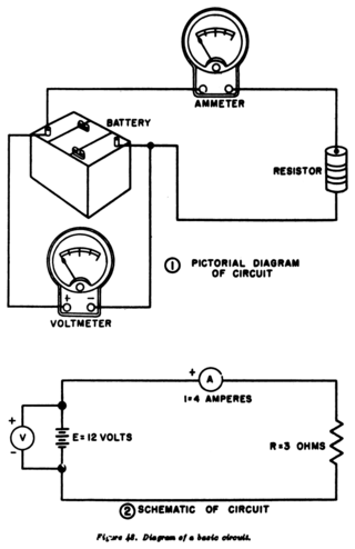
A circuit diagram is a graphical representation of an electrical circuit. A pictorial circuit diagram uses simple images of components, while a schematic diagram shows the components and interconnections of the circuit using standardized symbolic representations. The presentation of the interconnections between circuit components in the schematic diagram does not necessarily correspond to the physical arrangements in the finished device.

The input impedance of an electrical network is the measure of the opposition to current (impedance), both static (resistance) and dynamic (reactance), into the load that is external to the electrical source network. The input admittance is a measure of the load network's propensity to draw current. The source network is the portion of the network that transmits power, and the load network is the portion of the network that consumes power.

In power engineering, a single-line diagram (SLD), also sometimes called one-line diagram, is a simplest symbolic representation of an electric power system. A single line in the diagram typically corresponds to more than one physical conductor: in a direct current system the line includes the supply and return paths, in a three-phase system the line represents all three phases.

CADSTAR is a Windows-based electronic design automation (EDA) software tool for designing and creating schematic diagrams and printed circuit boards (PCBs). It provides engineers with a tool for designing simple or complex, multilayer PCBs. CADSTAR spans schematic capture, variant management, placement, automatic and high-speed routing, signal integrity, power integrity, EMC analysis, design rule checks and production of manufacturing data.

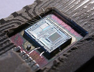
In semiconductor design, standard-cell methodology is a method of designing application-specific integrated circuits (ASICs) with mostly digital-logic features. Standard-cell methodology is an example of design abstraction, whereby a low-level very-large-scale integration (VLSI) layout is encapsulated into an abstract logic representation.

OrCAD Systems Corporation was a software company that made OrCAD, a proprietary software tool suite used primarily for electronic design automation (EDA). The software is used mainly by electronic design engineers and electronic technicians to create electronic schematics, and perform mixed-signal simulation and electronic prints for manufacturing printed circuit boards (PCBs). OrCAD was taken over by Cadence Design Systems in 1999 and was integrated with Cadence Allegro in 2005.

XCircuit is a Unix/X11 and Windows program for drawing publication-quality electrical circuit schematic diagrams and related figures and the production of circuit netlists through schematic capture. XCircuit regards circuits as inherently hierarchical and writes both PostScript output and hierarchical SPICE netlists. Circuit components are saved in and retrieved from libraries which are fully editable. XCircuit does not separate artistic expression from circuit drawing; it maintains flexibility in style without compromising the power of schematic capture.
In power engineering, nodal admittance matrix or Y Matrix or Ybus is an N x N matrix describing a linear power system with N buses. It represents the nodal admittance of the buses in a power system. In realistic systems which contain thousands of buses, the Y matrix is quite sparse. Each bus in a real power system is usually connected to only a few other buses through the transmission lines. The Y Matrix is also one of the data requirements needed to formulate a power-flow study.
The Layout Versus Schematic (LVS) is the class of electronic design automation (EDA) verification software that determines whether a particular integrated circuit layout corresponds to the original schematic or circuit diagram of the design.
An electronic circuit is composed of individual electronic components, such as resistors, transistors, capacitors, inductors and diodes, connected by conductive wires or traces through which electric current can flow. It is a type of electrical circuit and to be referred to as electronic, rather than electrical, generally at least one active component must be present. The combination of components and wires allows various simple and complex operations to be performed: signals can be amplified, computations can be performed, and data can be moved from one place to another.

A wiring diagram is a simplified conventional pictorial representation of an electrical circuit. It shows the components of the circuit as simplified shapes, and the power and signal connections between the devices.

Commensurate line circuits are electrical circuits composed of transmission lines that are all the same length; commonly one-eighth of a wavelength. Lumped element circuits can be directly converted to distributed-element circuits of this form by the use of Richards' transformation. This transformation has a particularly simple result; inductors are replaced with transmission lines terminated in short-circuits and capacitors are replaced with lines terminated in open-circuits. Commensurate line theory is particularly useful for designing distributed-element filters for use at microwave frequencies.

Electronics engineering is a sub-discipline of electrical engineering which emerged in the early 20th century and is distinguished by the additional use of active components such as semiconductor devices to amplify and control electric current flow. Previously electrical engineering only used passive devices such as mechanical switches, resistors, inductors, and capacitors.
Mechanical–electrical analogies are the representation of mechanical systems as electrical networks. At first, such analogies were used in reverse to help explain electrical phenomena in familiar mechanical terms. James Clerk Maxwell introduced analogies of this sort in the 19th century. However, as electrical network analysis matured it was found that certain mechanical problems could more easily be solved through an electrical analogy. Theoretical developments in the electrical domain that were particularly useful were the representation of an electrical network as an abstract topological diagram using the lumped element model and the ability of network analysis to synthesise a network to meet a prescribed frequency function.
The mobility analogy, also called admittance analogy or Firestone analogy, is a method of representing a mechanical system by an analogous electrical system. The advantage of doing this is that there is a large body of theory and analysis techniques concerning complex electrical systems, especially in the field of filters. By converting to an electrical representation, these tools in the electrical domain can be directly applied to a mechanical system without modification. A further advantage occurs in electromechanical systems: Converting the mechanical part of such a system into the electrical domain allows the entire system to be analysed as a unified whole.