
Diffraction is the interference or bending of waves around the corners of an obstacle or through an aperture into the region of geometrical shadow of the obstacle/aperture. The diffracting object or aperture effectively becomes a secondary source of the propagating wave. Italian scientist Francesco Maria Grimaldi coined the word diffraction and was the first to record accurate observations of the phenomenon in 1660.

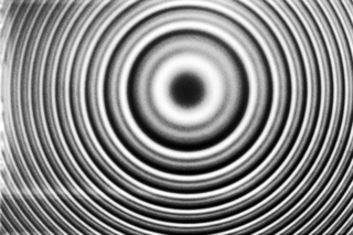
In physics, interference is a phenomenon in which two coherent waves are combined by adding their intensities or displacements with due consideration for their phase difference. The resultant wave may have greater intensity or lower amplitude if the two waves are in phase or out of phase, respectively. Interference effects can be observed with all types of waves, for example, light, radio, acoustic, surface water waves, gravity waves, or matter waves as well as in loudspeakers as electrical waves.
In physics, coherence length is the propagation distance over which a coherent wave maintains a specified degree of coherence. Wave interference is strong when the paths taken by all of the interfering waves differ by less than the coherence length. A wave with a longer coherence length is closer to a perfect sinusoidal wave. Coherence length is important in holography and telecommunications engineering.

In optics, a Gaussian beam is a beam of electromagnetic radiation with high monochromaticity whose amplitude envelope in the transverse plane is given by a Gaussian function; this also implies a Gaussian intensity (irradiance) profile. This fundamental (or TEM00) transverse Gaussian mode describes the intended output of most (but not all) lasers, as such a beam can be focused into the most concentrated spot. When such a beam is refocused by a lens, the transverse phase dependence is altered; this results in a different Gaussian beam. The electric and magnetic field amplitude profiles along any such circular Gaussian beam (for a given wavelength and polarization) are determined by a single parameter: the so-called waist w0. At any position z relative to the waist (focus) along a beam having a specified w0, the field amplitudes and phases are thereby determined as detailed below.
Interferometry is a technique which uses the interference of superimposed waves to extract information. Interferometry typically uses electromagnetic waves and is an important investigative technique in the fields of astronomy, fiber optics, engineering metrology, optical metrology, oceanography, seismology, spectroscopy, quantum mechanics, nuclear and particle physics, plasma physics, biomolecular interactions, surface profiling, microfluidics, mechanical stress/strain measurement, velocimetry, optometry, and making holograms.
In optics, a Fabry–Pérot interferometer (FPI) or etalon is an optical cavity made from two parallel reflecting surfaces. Optical waves can pass through the optical cavity only when they are in resonance with it. It is named after Charles Fabry and Alfred Perot, who developed the instrument in 1899. Etalon is from the French étalon, meaning "measuring gauge" or "standard".
In physics, coherence expresses the potential for two waves to interfere. Two monochromatic beams from a single source always interfere. Physical sources are not strictly monochromatic: they may be partly coherent. Beams from different sources are mutually incoherent.

The Mach–Zehnder interferometer is a device used to determine the relative phase shift variations between two collimated beams derived by splitting light from a single source. The interferometer has been used, among other things, to measure phase shifts between the two beams caused by a sample or a change in length of one of the paths. The apparatus is named after the physicists Ludwig Mach and Ludwig Zehnder; Zehnder's proposal in an 1891 article was refined by Mach in an 1892 article. Demonstrations of Mach–Zehnder interferometry with particles other than photons had been demonstrated as well in multiple experiments.

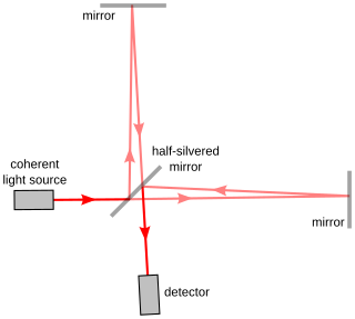
The Michelson interferometer is a common configuration for optical interferometry and was invented by the 19/20th-century American physicist Albert Abraham Michelson. Using a beam splitter, a light source is split into two arms. Each of those light beams is reflected back toward the beamsplitter which then combines their amplitudes using the superposition principle. The resulting interference pattern that is not directed back toward the source is typically directed to some type of photoelectric detector or camera. For different applications of the interferometer, the two light paths can be with different lengths or incorporate optical elements or even materials under test.
In optics, the Fraunhofer diffraction equation is used to model the diffraction of waves when plane waves are incident on a diffracting object, and the diffraction pattern is viewed at a sufficiently long distance from the object, and also when it is viewed at the focal plane of an imaging lens. In contrast, the diffraction pattern created near the diffracting object and is given by the Fresnel diffraction equation.
A collimator is a device which narrows a beam of particles or waves. To narrow can mean either to cause the directions of motion to become more aligned in a specific direction, or to cause the spatial cross section of the beam to become smaller.

The Sagnac effect, also called Sagnac interference, named after French physicist Georges Sagnac, is a phenomenon encountered in interferometry that is elicited by rotation. The Sagnac effect manifests itself in a setup called a ring interferometer or Sagnac interferometer. A beam of light is split and the two beams are made to follow the same path but in opposite directions. On return to the point of entry the two light beams are allowed to exit the ring and undergo interference. The relative phases of the two exiting beams, and thus the position of the interference fringes, are shifted according to the angular velocity of the apparatus. In other words, when the interferometer is at rest with respect to a nonrotating frame, the light takes the same amount of time to traverse the ring in either direction. However, when the interferometer system is spun, one beam of light has a longer path to travel than the other in order to complete one circuit of the mechanical frame, and so takes longer, resulting in a phase difference between the two beams. Georges Sagnac set up this experiment in 1913 in an attempt to prove the existence of the aether that Einstein's theory of special relativity makes superfluous.

An optical flat is an optical-grade piece of glass lapped and polished to be extremely flat on one or both sides, usually within a few tens of nanometres. They are used with a monochromatic light to determine the flatness of other surfaces, whether optical, metallic, ceramic, or otherwise, by interference. When an optical flat is placed on another surface and illuminated, the light waves reflect off both the bottom surface of the flat and the surface it is resting on. This causes a phenomenon similar to thin-film interference. The reflected waves interfere, creating a pattern of interference fringes visible as light and dark bands. The spacing between the fringes is smaller where the gap is changing more rapidly, indicating a departure from flatness in one of the two surfaces. This is comparable to the contour lines one would find on a map. A flat surface is indicated by a pattern of straight, parallel fringes with equal spacing, while other patterns indicate uneven surfaces. Two adjacent fringes indicate a difference in elevation of one-half wavelength of the light used, so by counting the fringes, differences in elevation of the surface can be measured to better than one micrometre.
Interference lithography is a technique for patterning regular arrays of fine features, without the use of complex optical systems or photomasks.
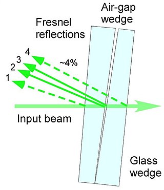
The air-wedge shearing interferometer is probably the simplest type of interferometer designed to visualize the disturbance of the wavefront after propagation through a test object. This interferometer is based on utilizing a thin wedged air-gap between two optical glass surfaces and can be used with virtually any light source even with non-coherent white light.
The wafer bond characterization is based on different methods and tests. Considered a high importance of the wafer are the successful bonded wafers without flaws. Those flaws can be caused by void formation in the interface due to unevenness or impurities. The bond connection is characterized for wafer bond development or quality assessment of fabricated wafers and sensors.
Self-mixing or back-injection laser interferometry is an interferometric technique in which a part of the light reflected by a vibrating target is reflected into the laser cavity, causing a modulation both in amplitude and in frequency of the emitted optical beam. In this way, the laser becomes sensitive to the distance traveled by the reflected beam thus becoming a distance, speed or vibration sensor. The advantage compared to a traditional measurement system is a lower cost thanks to the absence of collimation optics and external photodiodes.
A common-path interferometer is a class of interferometers in which the reference beam and sample beams travel along the same path. Examples include the Sagnac interferometer, Zernike phase-contrast interferometer, and the point diffraction interferometer. A common-path interferometer is generally more robust to environmental vibrations than a "double-path interferometer" such as the Michelson interferometer or the Mach–Zehnder interferometer. Although travelling along the same path, the reference and sample beams may travel along opposite directions, or they may travel along the same direction but with the same or different polarization.

As described here, white light interferometry is a non-contact optical method for surface height measurement on 3D structures with surface profiles varying between tens of nanometers and a few centimeters. It is often used as an alternative name for coherence scanning interferometry in the context of areal surface topography instrumentation that relies on spectrally-broadband, visible-wavelength light.
Optical holography is a technique which enables an optical wavefront to be recorded and later re-constructed. Holography is best known as a method of generating three-dimensional images but it also has a wide range of other applications.


