Spillway

Last updated
Chute spillway of Llyn Brianne dam in Wales Llyn Brianne spillway.jpg
Chute spillway of Llyn Brianne dam in Wales

A spillway is a structure used to provide the controlled release of water downstream from a dam or levee, typically into the riverbed of the dammed river itself. In the United Kingdom, they may be known as overflow channels. Spillways ensure that water does not damage parts of the structure not designed to convey water.

Contents

Spillways can include floodgates and fuse plugs to regulate water flow and reservoir level. Such features enable a spillway to regulate downstream flow—by releasing water in a controlled manner before the reservoir is full, operators can prevent an unacceptably large release later.

Other uses of the term "spillway" include bypasses of dams and outlets of channels used during high water, and outlet channels carved through natural dams such as moraines.

Water normally flows over a spillway only during flood periods, when the reservoir has reached its capacity and water continues entering faster than it can be released. In contrast, an intake tower is a structure used to control water release on a routine basis for purposes such as water supply and hydroelectricity generation.

Types

A spillway is located at the top of the reservoir pool. Dams may also have bottom outlets with valves or gates which may be operated to release flood flow, and a few dams lack overflow spillways and rely entirely on bottom outlets.

Cross-section of typical spillway with Tainter gates Bonneville Dam spillway cross-section.png
Cross-section of typical spillway with Tainter gates

The two main types of spillways are controlled and uncontrolled.

A controlled spillway has mechanical structures or gates to regulate the rate of flow. This design allows nearly the full height of the dam to be used for water storage year-round, and flood waters can be released as required by opening one or more gates.

An uncontrolled spillway, in contrast, does not have gates; when the water rises above the lip or crest of the spillway, it begins to be released from the reservoir. The rate of discharge is controlled only by the height of water above the reservoir's spillway. The fraction of storage volume in the reservoir above the spillway crest can only be used for the temporary storage of floodwater; it cannot be used as water supply storage because it sits higher than the dam can retain it.

In an intermediate type, normal level regulation of the reservoir is controlled by the mechanical gates. In this case, the dam is not designed to function with water flowing over the top if it, either due to the materials used for its construction or conditions directly downstream. If inflow to the reservoir exceeds the gate's capacity, an artificial channel called an auxiliary or emergency spillway will convey water. Often, that is intentionally blocked by a fuse plug. If present, the fuse plug is designed to wash out in case of a large flood, greater than the discharge capacity of the spillway gates. Although many months may be needed for construction crews to restore the fuse plug and channel after such an operation, the total damage and cost to repair is less than if the main water-retaining structures had been overtopped. The fuse plug concept is used where building a spillway with the required capacity would be costly.

Open channel spillway

Chute spillway

A chute spillway is a common and basic design that transfers excess water from behind the dam down a smooth decline into the river below. These are usually designed following an ogee curve. Most often, they are lined on the bottom and sides with concrete to protect the dam and topography. They may have a controlling device and some are thinner and multiply-lined if space and funding are tight. In addition, they are not always intended to dissipate energy like stepped spillways. Chute spillways can be ingrained with a baffle of concrete blocks but usually have a "flip lip" and/or dissipator basin, which creates a hydraulic jump, protecting the toe of the dam from erosion. [1]

Stepped spillway

A stepped chute baffled spillway of the Yeoman Hey Reservoir in the Peak District in England. YeomanHaySpillway.jpg
A stepped chute baffled spillway of the Yeoman Hey Reservoir in the Peak District in England.

Stepped channels and spillways have been used for over 3,000 years. [2] Despite being superseded by more modern engineering techniques such as hydraulic jumps in the mid twentieth century, since around 1985 [3] interest in stepped spillways and chutes has been renewed, partly due to the use of new construction materials (e.g. roller-compacted concrete, gabions) and design techniques (e.g. embankment overtopping protection). [4] [5] The steps produce considerable energy dissipation along the chute [6] and reduce the size of the required downstream energy dissipation basin. [7] [8]

Research is still active on the topic, with newer developments on embankment dam overflow protection systems, [8] converging spillways [9] and small weir design. [10]

Bell-mouth spillway

Vegetation has grown in the bell mouth spillway at Covao dos Conchos since its construction in 1955 such that it resembles a natural formation O Funil Dos Conchos.jpg
Vegetation has grown in the bell mouth spillway at Covão dos Conchos since its construction in 1955 such that it resembles a natural formation
Glory hole spillway in Lake Berryessa, California, in March 2017 Gloryhole in Lake Berryessa 1, March 2017.jpg
Glory hole spillway in Lake Berryessa, California, in March 2017

A bell-mouth spillway is designed like an inverted bell, where water can enter around the entire perimeter. [11] These uncontrolled spillways are also called morning glory (after the flower), or glory hole spillways. [12] [13] In areas where the surface of the reservoir may freeze, this type of spillway is normally fitted with ice-breaking arrangements to prevent the spillway from becoming ice-bound.

Some bell-mouth spillways are gate-controlled. The highest morning glory spillway in the world is at Hungry Horse Dam in Montana, U.S., and is controlled by a 64-by-12-foot (19.5 by 3.7 m) ring gate. [14] The bell-mouth spillway in Covão dos Conchos reservoir in Portugal is constructed to look like a natural formation. The largest bell-mouth spillway is in Geehi Dam, in New South Wales, Australia, measuring 105 ft (32 m) in diameter at the lake's surface. [15] [16] [17]

Siphon spillway

A siphon uses the difference in height between the intake and the outlet to create the pressure difference required to remove excess water. Siphons require priming to remove air in the bend for them to function, and most siphon spillways are designed to use water to automatically prime the siphon. One such design is the volute siphon, which employs volutes or fins on a funnel to form water into a vortex that draws air out of the system. The priming happens automatically when the water level rises above the inlets. [18]

Other types

The ogee crest over-tops a dam, a side channel wraps around the topography of a dam, and a labyrinth uses a zig-zag design to increase the sill length for a thinner design and increased discharge. A drop inlet resembles an intake for a hydroelectric power plant, and transfers water from behind the dam directly through tunnels to the river downstream. [19]

Design considerations

One parameter of spillway design is the largest flood it is designed to handle. The structures must safely withstand the appropriate spillway design flood (SDF), sometimes called the inflow design flood (IDF). The magnitude of the SDF may be set by dam safety guidelines, based on the size of the structure and the potential loss of human life or property downstream. The magnitude of the flood is sometimes expressed as a return period. A 100-year recurrence interval is the flood magnitude expected to be exceeded on the average of once in 100 years. This parameter may be expressed as an exceedance frequency with a 1% chance of being exceeded in any given year. The volume of water expected during the design flood is obtained by hydrologic calculations of the upstream watershed. The return period is set by dam safety guidelines, based on the size of the structure and the potential loss of human life or property downstream.

The United States Army Corps of Engineers bases their requirements on the probable maximum flood (PMF) [20] and the probable maximum precipitation (PMP). The PMP is the largest precipitation thought to be physically possible in the upstream watershed. [21] Dams of lower hazard may be allowed to have an IDF less than the PMF.

Energy dissipation

A U.S. Bureau of Reclamation type-III stilling basin USBORTypeIIIStillingBasin.gif
A U.S. Bureau of Reclamation type-III stilling basin

As water passes over a spillway and down the chute, potential energy converts into increasing kinetic energy. Failure to dissipate the water's energy can lead to scouring and erosion at the dam's toe (base). This can cause spillway damage and undermine the dam's stability. [22] To put this energy in perspective, the spillways at Tarbela Dam could, at full capacity, produce 40,000 MW; about 10 times the capacity of its power plant. [23]

The energy can be dissipated by addressing one or more parts of a spillway's design. [24]

Steps

First, on the spillway surface itself by a series of steps along the spillway (see stepped spillway). [5]

Flip bucket

Second, at the base of a spillway, a flip bucket can create a hydraulic jump and deflect water upwards.

Ski jump

A ski jump can direct water horizontally and eventually down into a plunge pool, or two ski jumps can direct their water discharges to collide with one another. [5] [23]

Stilling basin

Third, a stilling basin at the terminus of a spillway serves to further dissipate energy and prevent erosion. They are usually filled with a relatively shallow depth of water and sometimes lined with concrete. A number of velocity-reducing components can be incorporated into their design to include chute blocks, baffle blocks, wing walls, surface boils, or end sills. [25]

Safety

Spillway gates may operate suddenly without warning, under remote control. Trespassers within the spillway are at high risk of drowning. Spillways are usually fenced and equipped with locked gates to prevent casual trespassing within the structure. Warning signs, sirens, and other measures may be in place to warn users of the downstream area of sudden release of water. Operating protocols may require "cracking" a gate to release a small amount of water to warn persons downstream.

The sudden closure of a spillway gate can result in the stranding of fish, and this is usually avoided.

See also

Related Research Articles

<span class="mw-page-title-main">Dartmouth Dam</span> Dam in Victoria

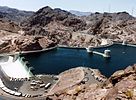
Dartmouth Dam is a large rock-fill embankment dam with an uncontrolled chute spillway across the Mitta Mitta, Gibbo and Dart rivers, the Morass Creek and a number of small tributaries. The dam is located near Mount Bogong in the north-east of the Australian state of Victoria. The dam's purpose includes irrigation, the generation of hydro-electric power, water supply and conservation. The impounded reservoir is called Dartmouth Reservoir, sometimes called Lake Dartmouth. The Dartmouth Power Station, a hydro-electric power station that generates power to the national grid, is located near the dam wall.

<span class="mw-page-title-main">Dam</span> Barrier that stops or restricts the flow of surface or underground streams

A dam is a barrier that stops or restricts the flow of surface water or underground streams. Reservoirs created by dams not only suppress floods but also provide water for activities such as irrigation, human consumption, industrial use, aquaculture, and navigability. Hydropower is often used in conjunction with dams to generate electricity. A dam can also be used to collect or store water which can be evenly distributed between locations. Dams generally serve the primary purpose of retaining water, while other structures such as floodgates or levees are used to manage or prevent water flow into specific land regions.

<span class="mw-page-title-main">Hydraulic jump</span> Discharge of high velocity liquid into lower velocity area

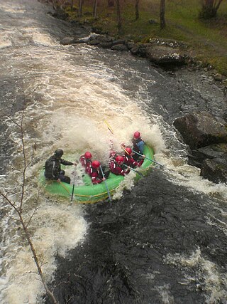
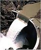
A hydraulic jump is a phenomenon in the science of hydraulics which is frequently observed in open channel flow such as rivers and spillways. When liquid at high velocity discharges into a zone of lower velocity, a rather abrupt rise occurs in the liquid surface. The rapidly flowing liquid is abruptly slowed and increases in height, converting some of the flow's initial kinetic energy into an increase in potential energy, with some energy irreversibly lost through turbulence to heat. In an open channel flow, this manifests as the fast flow rapidly slowing and piling up on top of itself similar to how a shockwave forms.

<span class="mw-page-title-main">Glenbawn Dam</span> Dam in Hunter Valley, New South Wales

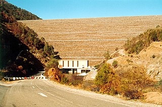
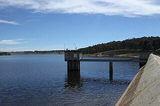
Glenbawn Dam is a major ungated earth and rock fill with clay core embankment dam with concrete chute spillway plus fuse plugs across the Hunter River upstream of Aberdeen in the Hunter Valley of New South Wales, Australia. The dam's purpose includes flood mitigation, hydro-electric power, irrigation, water supply and conservation. The impounded reservoir is called Lake Glenbawn.

<span class="mw-page-title-main">Floodgate</span> Adjustable gate used to control water flow

Floodgates, also called stop gates, are adjustable gates used to control water flow in flood barriers, reservoir, river, stream, or levee systems. They may be designed to set spillway crest heights in dams, to adjust flow rates in sluices and canals, or they may be designed to stop water flow entirely as part of a levee or storm surge system. Since most of these devices operate by controlling the water surface elevation being stored or routed, they are also known as crest gates. In the case of flood bypass systems, floodgates sometimes are also used to lower the water levels in a main river or canal channels by allowing more water to flow into a flood bypass or detention basin when the main river or canal is approaching a flood stage.

<span class="mw-page-title-main">Copeton Dam</span> Dam in New South Wales, Australia

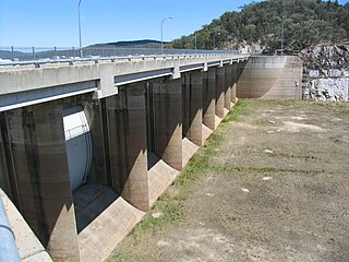
Copeton Dam is a major clay core and rock fill embankment dam with nine radial gates and a gated concrete chute spillway across the Gwydir River upstream of Bingara in the New England region of New South Wales, Australia. The dam's purpose includes environmental flows, hydro-electric power generation, irrigation, and water supply. The impounded reservoir is called Lake Copeton.

<span class="mw-page-title-main">New Waddell Dam</span> Dam in Maricopa County, Arizona

The New Waddell Dam is an embankment dam on the Agua Fria River in Maricopa County, Arizona, 35 miles (56 km) northwest of Phoenix. It serves as part of the Central Arizona Project (CAP) while also providing water for the Maricopa Water District. The dam creates Lake Pleasant with water from the Agua Fria and also the CAP aqueduct. In addition, it affords flood protection, hydroelectric power production and recreational opportunities. Construction on the dam began in 1985 and ended in 1994. Its reservoir submerged the Old Waddell Dam which was completed in 1927 after decades of planning.

<span class="mw-page-title-main">Embankment dam</span> Type of artificial dam

An embankment dam is a large artificial dam. It is typically created by the placement and compaction of a complex semi-plastic mound of various compositions of soil or rock. It has a semi-pervious waterproof natural covering for its surface and a dense, impervious core. This makes the dam impervious to surface or seepage erosion. Such a dam is composed of fragmented independent material particles. The friction and interaction of particles binds the particles together into a stable mass rather than by the use of a cementing substance.

In hydraulic engineering, a nappe is a sheet or curtain of water that flows over a weir or dam. The upper and lower water surface have well-defined characteristics that are created by the crest of a dam or weir. Both structures have different features that characterize how a nappe might flow through or over impervious concrete structures. Hydraulic engineers distinguish these two water structures in characterizing and calculating the formation of a nappe. Engineers account for the bathymetry of standing bodies or moving bodies of water. An appropriate crest is built for the dam or weir so that dam failure is not caused by nappe vibration or air cavitation from free-overall structures.

<span class="mw-page-title-main">Drop structure</span> Structure that lowers elevation of water in a controlled fashion

A drop structure, also known as a grade control, sill, or weir, is a manmade structure, typically small and built on minor streams, or as part of a dam's spillway, to pass water to a lower elevation while controlling the energy and velocity of the water as it passes over. Unlike most dams, drop structures are usually not built for water impoundment, diversion, or raising the water level. Mostly built on watercourses with steep gradients, they serve other purposes such as water oxygenation and erosion prevention.

<span class="mw-page-title-main">Darbandikhan Dam</span> Dam in Darbandikhan, Kurdistan Region.

The Darbandikhan Dam is a multi-purpose embankment dam on the Diyala River in northern Sulaymaniyah Governorate, Iraq. It was constructed between 1956 and 1961. The purpose of the dam is irrigation, flood control, hydroelectric power production and recreation. Due to poor construction and neglect, the dam and its 249 MW power station have undergone several repairs over the years. A rehabilitation of the power station began in 2007 and was completed in 2013.

<span class="mw-page-title-main">Hubert Chanson</span> Australian engineering academic (born 1961)

Hubert Chanson is a professional engineer and academic in hydraulic engineering and environmental fluid mechanics. Since 1990 he has worked at the University of Queensland.

<span class="mw-page-title-main">New Exchequer Dam</span> Dam in Mariposa County, California

New Exchequer Dam is a concrete–faced, rock-fill dam on the Merced River in central California in the United States. It forms Lake McClure, which impounds the river for irrigation and hydroelectric power production and has a capacity of more than 1,000,000 acre-feet (1.2 km3). The Merced Irrigation District (MID) operates the dam and was also responsible for its construction.

<span class="mw-page-title-main">Stepped spillway</span> Structure for energy dissipated release of flows from a dam or levee

A stepped spillway is a spillway with steps on the spillway chute to assist in the dissipation of the kinetic energy of the descending water. This eliminates or reduces the need for an additional energy dissipator, such as a body of water, at the end of the spillway downstream.

<span class="mw-page-title-main">Oderteich</span> Dam in Lower Saxony

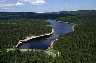
The Oderteich is an historic reservoir about seven kilometres northeast of Sankt Andreasberg in the Upper Harz in central Germany. It was built by miners from St. Andreasberg in the years 1715 to 1722 and, today, is an important component of the water supply network known as the Upper Harz Water Regale. Moreover, for 170 years, from the time it was completed to the end of the 19th century, the Oderteich had the largest dam in Germany. The dam lies at a height of 725 m above NN by the B 242 federal highway, about a kilometre west of its intersection with the B 4.

<span class="mw-page-title-main">Zengwen Dam</span> Dam in Dapu, Chiyai County, Taiwan

Zengwen Dam, also spelled Tsengwen Dam, is a major earthen dam in Dapu Township, Chiayi County, Taiwan on the Zengwen River. It is the third tallest dam in Taiwan, and forms Zengwen Reservoir (曾文水庫), the biggest reservoir in Taiwan by volume. The dam stores water for irrigation of the Chianan Plain, Taiwan's most productive agricultural region, and provides flood control along the Zengwen River which flows through Tainan City. The dam supports a 50 megawatt hydroelectric power station.

The Dikgatlhong Dam is a dam near the village of Robelela on the Shashe River in Botswana, completed in December 2011. When full it will hold 400,000,000 cubic metres (1.4×10¹⁰ cu ft). The next largest dam in Botswana, the Gaborone Dam, has capacity of 141,000,000 cubic metres (5.0×10⁹ cu ft).

<span class="mw-page-title-main">Oberon Dam</span> Dam in Central Tablelands, New South Wales

Oberon Dam or Fish River Dam is a major ungated concrete slab and buttress with earth embankment dam comprising a concrete ski jump chute spillway and fuse plug across the Fish River upstream of Oberon in the Central Tablelands region of New South Wales, Australia. The dam's purpose includes flood mitigation, industrial, and water supply. The impounded reservoir is called Lake Oberon.

<span class="mw-page-title-main">Open channel spillway</span>

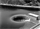
Open channel spillways are dam spillways that utilize the principles of open-channel flow to convey impounded water in order to prevent dam failure. They can function as principal spillways, emergency spillways, or both. They can be located on the dam itself or on a natural grade in the vicinity of the dam.

<span class="mw-page-title-main">Oroville Dam crisis</span> Potential failure during 2017 rainstorm

In February 2017, heavy rainfall damaged Oroville Dam's main and emergency spillways, prompting the evacuation of more than 180,000 people living downstream along the Feather River and the relocation of a fish hatchery.

References

  1. Henry H., Thomas. "Chute spillways, The Engineering of Large Dams". Archived from the original on 9 April 2010. Retrieved 2010-07-05.
  2. H. Chanson (2001–2002). "Historical Development of Stepped Cascades for the Dissipation of Hydraulic Energy". Transactions of the Newcomen Society. 71 (2): 295–318.
  3. H. Chanson (2000). "Hydraulics of Stepped Spillways: Current Status" (PDF). Journal of Hydraulic Engineering. 126 (9): 636–637. doi:10.1061/(ASCE)0733-9429(2000)126:9(636). ISSN   0733-9429.
  4. H. Chanson (1995). Hydraulic Design of Stepped Cascades, Channels, Weirs and Spillways. Pergamon. ISBN   978-0-08-041918-3.
  5. 1 2 3 H. Chanson (2002). The Hydraulics of Stepped Chutes and Spillways. Balkema. ISBN   978-90-5809-352-3.
  6. Rajaratnam, N. (1990). "Skimming Flow in Stepped Spillways". Journal of Hydraulic Engineering. 116 (4): 587–591. doi:10.1061/(ASCE)0733-9429(1990)116:4(587).
  7. Chanson, H. (2001). "Hydraulic Design of Stepped Spillways and Downstream Energy Dissipators" (PDF). Dam Engineering. 11 (4): 205–242.
  8. 1 2 Gonzalez, C.A.; Chanson, H. (2007). "Hydraulic Design of Stepped Spillways and Downstream Energy Dissipators for Embankment Dams" (PDF). Dam Engineering. 17 (4): 223–244.
  9. S.L. Hunt, S.R. Abt & D.M. Temple (2008). Hydraulic Design of Stepped Spillways and Downstream Energy Dissipators for Embankment Dams. Impact of Converging Chute Walls for Roller Compacted Concrete Stepped Spillways.
  10. I. Meireles; J. Cabrita; J. Matos (2006). Non-Aerated Skimming Flow Properties on Stepped Chutes over Small Embankment Dams in Hydraulic Structures: a Challenge to Engineers and Researchers, Proceedings of the International Junior Researcher and Engineer Workshop on Hydraulic Structures. St. Lucia, Qld.: University of Queensland, Division of Civil Engineering. p. 205. ISBN   978-1-86499-868-9.
  11. Ratnayaka, Don D.; Brandt, Malcolm J.; Johnson, K. Michael (2009). Twort's water supply (6th ed.). Oxford: Butterworth-Heinemann. p. 177. ISBN   978-0-7506-6843-9.
  12. Sabeti, Parham; Karami, Hojat; Sarkardeh, Hamed (2019-06-30). "Analysis of the Impact of Effective Length of Morning Glory Spillway on Its Performance (Numerical Study)". Instrumentation Mesure Métrologie. 18 (2): 211–221. doi: 10.18280/i2m.180217 .
  13. "Lake Berryessa, Bureau of Reclamation, Mid-Pacific Region". Dept. of Interior. 2017-12-15. Retrieved 2019-03-08.
  14. "Hungry Horse Dam". U.S. Bureau of Reclamation. Archived from the original on 13 June 2011. Retrieved 1 November 2010.
  15. "Dams". Archived from the original on 2013-05-03. Retrieved 2016-10-04.
  16. Stene, Eric A. "Hungry Horse Project History" (PDF). U.S. Bureau of Reclamation. Retrieved 1 November 2010.
  17. Storey, Brit Allan (2008). The Bureau of Reclamation: history essays from the centennial symposium, Volume 1. United States Government Printing Office. p. 36. ISBN   978-0-16-081822-6 . Retrieved 1 November 2010.
  18. Rao, Govinda NS (2008). "Design of Volute Siphon" (PDF). Journal of the Indian Institute of Science. 88 (3): 915–930. Archived from the original (PDF) on 2013-12-20. Retrieved 2013-12-19.
  19. "Hydraulic Design, Types of Spillways" (PDF). Rowan University. Retrieved 2010-07-05.
  20. "INFLOW DESIGN FLOODS FOR DAMS AND RESERVOIRS" (PDF). USACE. Retrieved 5 April 2019.
  21. "Manual on Estimation of Probable Maximum Precipitation (PMP)" (PDF). WMO. p. 26. Retrieved 5 April 2019.
  22. Punmia (1992). Irrigation and Water Power Engineering. Firewall Media. pp. 500–501. ISBN   978-81-7008-084-8.
  23. 1 2 Novak, P. (2008). Hydraulic structures (4. ed., repr. ed.). London [u.a.]: Taylor & Francis. pp. 244–260. ISBN   978-0-415-38625-8.
  24. Chanson, H. (2015). Energy Dissipation in Hydraulic Structures. IAHR Monograph, CRC Press, Taylor & Francis Group, Leiden, The Netherlands, 168 pages. ISBN   978-1-138-02755-8.
  25. Hager, Willi H. (1992). Energy dissipators and hydraulic jump. Dordrecht u.a.: Kluwer. pp. 213–218. ISBN   978-0-7923-1508-7.