
The characteristic impedance or surge impedance (usually written Z0) of a uniform transmission line is the ratio of the amplitudes of voltage and current of a single wave propagating along the line; that is, a wave travelling in one direction in the absence of reflections in the other direction. Alternatively, and equivalently, it can be defined as the input impedance of a transmission line when its length is infinite. Characteristic impedance is determined by the geometry and materials of the transmission line and, for a uniform line, is not dependent on its length. The SI unit of characteristic impedance is the ohm.
The propagation constant of a sinusoidal electromagnetic wave is a measure of the change undergone by the amplitude and phase of the wave as it propagates in a given direction. The quantity being measured can be the voltage, the current in a circuit, or a field vector such as electric field strength or flux density. The propagation constant itself measures the change per unit length, but it is otherwise dimensionless. In the context of two-port networks and their cascades, propagation constant measures the change undergone by the source quantity as it propagates from one port to the next.

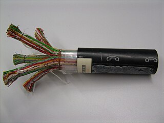
In electrical engineering, a transmission line is a specialized cable or other structure designed to conduct electromagnetic waves in a contained manner. The term applies when the conductors are long enough that the wave nature of the transmission must be taken into account. This applies especially to radio-frequency engineering because the short wavelengths mean that wave phenomena arise over very short distances. However, the theory of transmission lines was historically developed to explain phenomena on very long telegraph lines, especially submarine telegraph cables.

In electrical engineering, impedance is the opposition to alternating current presented by the combined effect of resistance and reactance in a circuit.
The electrical resistance of an object is a measure of its opposition to the flow of electric current. Its reciprocal quantity is electrical conductance, measuring the ease with which an electric current passes. Electrical resistance shares some conceptual parallels with mechanical friction. The SI unit of electrical resistance is the ohm, while electrical conductance is measured in siemens (S).
In electrical circuits, reactance is the opposition presented to alternating current by inductance and,or capacitance. Greater reactance gives smaller current for the same applied voltage. Reactance is similar to resistance in this respect, but does not lead to dissipation of electrical energy as heat; instead, energy is momentarily stored in the reactance, and a quarter-cycle later returned to the circuit.
In electrical engineering, admittance is a measure of how easily a circuit or device will allow a current to flow. It is defined as the reciprocal of impedance, analogous to how conductance & resistance are defined. The SI unit of admittance is the siemens ; the older, synonymous unit is mho, and its symbol is ℧. Oliver Heaviside coined the term admittance in December 1887. Heaviside used Y to represent the magnitude of admittance, but it quickly became the conventional symbol for admittance itself through the publications of Charles Proteus Steinmetz. Heaviside probably chose Y simply because it is next to Z in the alphabet, the conventional symbol for impedance.

A gyrator is a passive, linear, lossless, two-port electrical network element proposed in 1948 by Bernard D. H. Tellegen as a hypothetical fifth linear element after the resistor, capacitor, inductor and ideal transformer. Unlike the four conventional elements, the gyrator is non-reciprocal. Gyrators permit network realizations of two-(or-more)-port devices which cannot be realized with just the conventional four elements. In particular, gyrators make possible network realizations of isolators and circulators. Gyrators do not however change the range of one-port devices that can be realized. Although the gyrator was conceived as a fifth linear element, its adoption makes both the ideal transformer and either the capacitor or inductor redundant. Thus the number of necessary linear elements is in fact reduced to three. Circuits that function as gyrators can be built with transistors and op-amps using feedback.

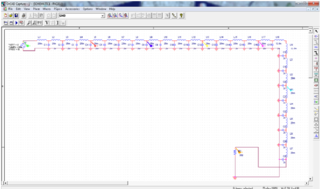
The Smith chart, invented by Phillip H. Smith (1905–1987) and independently by Mizuhashi Tosaku, is a graphical calculator or nomogram designed for electrical and electronics engineers specializing in radio frequency (RF) engineering to assist in solving problems with transmission lines and matching circuits. The Smith chart can be used to simultaneously display multiple parameters including impedances, admittances, reflection coefficients, scattering parameters, noise figure circles, constant gain contours and regions for unconditional stability, including mechanical vibrations analysis. The Smith chart is most frequently used at or within the unity radius region. However, the remainder is still mathematically relevant, being used, for example, in oscillator design and stability analysis. While the use of paper Smith charts for solving the complex mathematics involved in matching problems has been largely replaced by software based methods, the Smith chart is still a very useful method of showing how RF parameters behave at one or more frequencies, an alternative to using tabular information. Thus most RF circuit analysis software includes a Smith chart option for the display of results and all but the simplest impedance measuring instruments can plot measured results on a Smith chart display.
Acoustic impedance and specific acoustic impedance are measures of the opposition that a system presents to the acoustic flow resulting from an acoustic pressure applied to the system. The SI unit of acoustic impedance is the pascal-second per cubic metre, or in the MKS system the rayl per square metre, while that of specific acoustic impedance is the pascal-second per metre, or in the MKS system the rayl. There is a close analogy with electrical impedance, which measures the opposition that a system presents to the electric current resulting from a voltage applied to the system.
The Heaviside condition, named for Oliver Heaviside (1850–1925), is the condition an electrical transmission line must meet in order for there to be no distortion of a transmitted signal. Also known as the distortionless condition, it can be used to improve the performance of a transmission line by adding loading to the cable.
Foster's reactance theorem is an important theorem in the fields of electrical network analysis and synthesis. The theorem states that the reactance of a passive, lossless two-terminal (one-port) network always strictly monotonically increases with frequency. It is easily seen that the reactances of inductors and capacitors individually increase with frequency and from that basis a proof for passive lossless networks generally can be constructed. The proof of the theorem was presented by Ronald Martin Foster in 1924, although the principle had been published earlier by Foster's colleagues at American Telephone & Telegraph.

The gyrator–capacitor model - sometimes also the capacitor-permeance model - is a lumped-element model for magnetic circuits, that can be used in place of the more common resistance–reluctance model. The model makes permeance elements analogous to electrical capacitance rather than electrical resistance. Windings are represented as gyrators, interfacing between the electrical circuit and the magnetic model.
The primary line constants are parameters that describe the characteristics of conductive transmission lines, such as pairs of copper wires, in terms of the physical electrical properties of the line. The primary line constants are only relevant to transmission lines and are to be contrasted with the secondary line constants, which can be derived from them, and are more generally applicable. The secondary line constants can be used, for instance, to compare the characteristics of a waveguide to a copper line, whereas the primary constants have no meaning for a waveguide.
Characteristic admittance is the mathematical inverse of the characteristic impedance. The general expression for the characteristic admittance of a transmission line is:

An RLC circuit is an electrical circuit consisting of a resistor (R), an inductor (L), and a capacitor (C), connected in series or in parallel. The name of the circuit is derived from the letters that are used to denote the constituent components of this circuit, where the sequence of the components may vary from RLC.

The open-circuit test, or no-load test, is one of the methods used in electrical engineering to determine the no-load impedance in the excitation branch of a transformer. The no load is represented by the open circuit, which is represented on the right side of the figure as the "hole" or incomplete part of the circuit.
The mobility analogy, also called admittance analogy or Firestone analogy, is a method of representing a mechanical system by an analogous electrical system. The advantage of doing this is that there is a large body of theory and analysis techniques concerning complex electrical systems, especially in the field of filters. By converting to an electrical representation, these tools in the electrical domain can be directly applied to a mechanical system without modification. A further advantage occurs in electromechanical systems: Converting the mechanical part of such a system into the electrical domain allows the entire system to be analysed as a unified whole.
Performance modelling is the abstraction of a real system into a simplified representation to enable the prediction of performance. The creation of a model can provide insight into how a proposed or actual system will or does work. This can, however, point towards different things to people belonging to different fields of work.
The transformer ratio arm bridge or TRA bridge is a type of bridge circuit used for measuring electronic components, using a.c. It can be designed to work in terms of either impedance or admittance. It can be used on resistors, capacitors and inductors, measuring minor as well as major terms, e.g. series resistance in capacitors. It is probably the most accurate type of bridge available, being capable of the precision needed, for example, when checking secondary component standards against national standards.


