Related Research Articles

Medium wave (MW) is the part of the medium frequency (MF) radio band used mainly for AM radio broadcasting. The spectrum provides about 120 channels with more limited sound quality than FM stations on the FM broadcast band. During the daytime, reception is usually limited to more local stations, though this is dependent on the signal conditions and quality of radio receiver used. Improved signal propagation at night allows the reception of much longer distance signals. This can cause increased interference because on most channels multiple transmitters operate simultaneously worldwide. In addition, amplitude modulation (AM) is often more prone to interference by various electronic devices, especially power supplies and computers. Strong transmitters cover larger areas than on the FM broadcast band but require more energy and longer antennas. Digital modes are possible but have not reached momentum yet.
Low frequency (LF) is the ITU designation for radio frequencies (RF) in the range of 30–300 kHz. Since its wavelengths range from 10–1 km, respectively, it is also known as the kilometre band or kilometre wave.

In radio, longwave, long wave or long-wave, and commonly abbreviated LW, refers to parts of the radio spectrum with wavelengths longer than what was originally called the medium-wave broadcasting band. The term is historic, dating from the early 20th century, when the radio spectrum was considered to consist of longwave (LW), medium-wave (MW), and short-wave (SW) radio bands. Most modern radio systems and devices use wavelengths which would then have been considered 'ultra-short'.

In radio engineering, an antenna or aerial is the interface between radio waves propagating through space and electric currents moving in metal conductors, used with a transmitter or receiver. In transmission, a radio transmitter supplies an electric current to the antenna's terminals, and the antenna radiates the energy from the current as electromagnetic waves. In reception, an antenna intercepts some of the power of a radio wave in order to produce an electric current at its terminals, that is applied to a receiver to be amplified. Antennas are essential components of all radio equipment.

Effective radiated power (ERP), synonymous with equivalent radiated power, is an IEEE standardized definition of directional radio frequency (RF) power, such as that emitted by a radio transmitter. It is the total power in watts that would have to be radiated by a half-wave dipole antenna to give the same radiation intensity as the actual source antenna at a distant receiver located in the direction of the antenna's strongest beam. ERP measures the combination of the power emitted by the transmitter and the ability of the antenna to direct that power in a given direction. It is equal to the input power to the antenna multiplied by the gain of the antenna. It is used in electronics and telecommunications, particularly in broadcasting to quantify the apparent power of a broadcasting station experienced by listeners in its reception area.
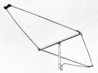
A rhombic antenna is made of four sections of wire suspended parallel to the ground in a diamond or "rhombus" shape. Each of the four sides is the same length – about a quarter-wavelength to one wavelength per section – converging but not touching at an angle of about 42° at the fed end and at the far end. The length is not critical, typically from one to two wavelengths (λ), but there is an optimum angle for any given length and frequency. A horizontal rhombic antenna radiates horizontally polarized radio waves at a low elevation angle off the pointy ends of the antenna.

Direction finding (DF), or radio direction finding (RDF), is – in accordance with International Telecommunication Union (ITU) – defined as radio location that uses the reception of radio waves to determine the direction in which a radio station or an object is located. This can refer to radio or other forms of wireless communication, including radar signals detection and monitoring (ELINT/ESM). By combining the direction information from two or more suitably spaced receivers, the source of a transmission may be located via triangulation. Radio direction finding is used in the navigation of ships and aircraft, to locate emergency transmitters for search and rescue, for tracking wildlife, and to locate illegal or interfering transmitters. RDF was important in combating German threats during both the World War II Battle of Britain and the long running Battle of the Atlantic. In the former, the Air Ministry also used RDF to locate its own fighter groups and vector them to detected German raids.

The Beverage antenna or "wave antenna" is a long-wire receiving antenna mainly used in the low frequency and medium frequency radio bands, invented by Harold H. Beverage in 1921. It is used by amateur radio, shortwave listening, and longwave radio DXers and military applications.

Radio masts and towers are typically tall structures designed to support antennas for telecommunications and broadcasting, including television. There are two main types: guyed and self-supporting structures. They are among the tallest human-made structures. Masts are often named after the broadcasting organizations that originally built them or currently use them.
A mast radiator is a radio mast or tower in which the metal structure itself is energized and functions as an antenna. This design, first used widely in the 1930s, is commonly used for transmitting antennas operating at low frequencies, in the LF and MF bands, in particular those used for AM radio broadcasting stations. The conductive steel mast is electrically connected to the transmitter. Its base is usually mounted on a nonconductive support to insulate it from the ground. A mast radiator is a form of monopole antenna.
A broadcast transmitter is an electronic device which radiates radio waves modulated with information content intended to be received by the general public. Examples are a radio broadcasting transmitter which transmits audio (sound) to broadcast radio receivers (radios) owned by the public, or a television transmitter, which transmits moving images (video) to television receivers (televisions). The term often includes the antenna which radiates the radio waves, and the building and facilities associated with the transmitter. A broadcasting station consists of a broadcast transmitter along with the production studio which originates the broadcasts. Broadcast transmitters must be licensed by governments, and are restricted to specific frequencies and power levels. Each transmitter is assigned a unique identifier consisting of a string of letters and numbers called a callsign, which must be used in all broadcasts.

A television antenna is an antenna specifically designed for use with a television receiver (TV) to receive over-the-air broadcast television signals from a television station. Television reception is dependent upon the antenna as well as the transmitter. Terrestrial television is broadcast on frequencies from about 47 to 250 MHz in the very high frequency (VHF) band, and 470 to 960 MHz in the ultra high frequency (UHF) band in different countries. Television antennas are manufactured in two different types: "indoor" antennas, to be located on top of or next to the television set, and "outdoor" antennas, mounted on a mast on top of the owner's house. They can also be mounted in a loft or attic, where the dry conditions and increased elevation are advantageous for reception and antenna longevity. Outdoor antennas are more expensive and difficult to install, but are necessary for adequate reception in fringe areas far from television stations. The most common types of indoor antennas are the dipole and loop antennas, and for outdoor antennas the Yagi, log periodic, and for UHF channels the multi-bay reflective array antenna.

An umbrella antenna is a capacitively top-loaded wire monopole antenna, consisting in most cases of a mast fed at the ground end, to which a number of radial wires are connected at the top, sloping downwards. They are used as transmitting antennas below 1 MHz, in the MF, LF and particularly the VLF bands, at frequencies sufficiently low that it is impractical or infeasible to build a full size quarter-wave monopole antenna. The outer end of each radial wire, sloping down from the top of the antenna, is connected by an insulator to a supporting rope or (usually) insulated cable anchored to the ground; the radial wires can also support the mast as guy wires. The radial wires make the antenna look like the wire frame of a giant umbrella hence the name.

Nauen Transmitter Station in Nauen, Havelland district, Brandenburg, Germany, is the oldest continuously operating radio transmitting installation in the world. Germany's first high power radio transmitter, it was founded on 1 April 1906 by Telefunken corporation and operated as a longwave radiotelegraphy station through World War II, and during World War I became Germany's main link with the outside world when its submarine communications cables were cut. Upgraded with shortwave transmitters in the 1920s it was Germany's most advanced long range radio station, continually upgraded with the latest equipment and serving as an experimental station for Telefunken to test new technology. At the end of World War II, invading Russian troops dismantled and removed the transmitting equipment. During the Cold War it served as the GDR's international shortwave station Radio Berlin International (RBI), and was the East Bloc's second most powerful radio station, disseminating Communist propaganda to other countries. Since German Reunification in 1991 it has been operated by Deutsche Telekom, Germany's state telecommunication service. The original 1920 transmitter building designed by architect Herman Muthesius is still used; it is the only remaining building designed by that architect.

Radio is the technology of signaling and communicating using radio waves. Radio waves are electromagnetic waves of frequency between 3 hertz (Hz) and 300 gigahertz (GHz). They are generated by an electronic device called a transmitter connected to an antenna which radiates the waves, and received by another antenna connected to a radio receiver. Radio is widely used in modern technology, in radio communication, radar, radio navigation, remote control, remote sensing, and other applications.

The Adcock antenna is an antenna array consisting of four equidistant vertical elements which can be used to transmit or receive directional radio waves.

An antenna array is a set of multiple connected antennas which work together as a single antenna, to transmit or receive radio waves. The individual antennas are usually connected to a single receiver or transmitter by feedlines that feed the power to the elements in a specific phase relationship. The radio waves radiated by each individual antenna combine and superpose, adding together to enhance the power radiated in desired directions, and cancelling to reduce the power radiated in other directions. Similarly, when used for receiving, the separate radio frequency currents from the individual antennas combine in the receiver with the correct phase relationship to enhance signals received from the desired directions and cancel signals from undesired directions. More sophisticated array antennas may have multiple transmitter or receiver modules, each connected to a separate antenna element or group of elements.
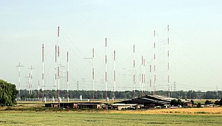
Curtain arrays are a class of large multielement directional radio transmitting wire antennas, used in the shortwave radio bands. They are a type of reflective array antenna, consisting of multiple wire dipole antennas, suspended in a vertical plane, often in front of a "curtain" reflector made of a flat vertical screen of many long parallel wires. These are suspended by support wires strung between pairs of tall steel towers, up to 90 m high. They are used for long-distance skywave transmission; they transmit a beam of radio waves at a shallow angle into the sky just above the horizon, which is reflected by the ionosphere back to Earth beyond the horizon. Curtain antennas are mostly used by international short wave radio stations to broadcast to large areas at transcontinental distances.

A Bellini–Tosi direction finder is a type of radio direction finder (RDF), which determines the direction to, or bearing of, a radio transmitter. Earlier RDF systems used very large rotating loop antennas, which the B–T system replaced with two fixed antennae and a small rotating loop, known as a radiogoniometer. This made RDF much more practical, especially on large vehicles like ships or when using very long wavelengths that demand large antennae.
In radio systems, many different antenna types are used whose properties are especially crafted for particular applications. Antennas can be classified in various ways. The list below groups together antennas under common operating principles, following the way antennas are classified in many engineering textbooks.
References
- ↑ Jacoby Barrera (2019). Broadcasting Journalism. EDTECH. pp. 129–132. ISBN 9781839472893.
- ↑ John S. Seybold (2005). Introduction to RF Propagation. Wiley. p. 54. ISBN 9780471743682.
- ↑ Graham A. Jones; David H. Layer; Thomas G. Osenkowsky; Edmund A. Williams (2013). National Association of Broadcasters Engineering Handbook: NAB Engineering Handbook. Taylor & Francis. p. 759. ISBN 9781136034107.
- ↑ B. Whitfield Griffith (2000). Radio-electronic Transmission Fundamentals. Noble Publishing Corporation. pp. 411–419. ISBN 9781884932137.
| | This mast or transmitter tower article is a stub. You can help Wikipedia by expanding it. |