Transmission of water waves over a coastal structure
Wave overtopping in Vlissingen during a storm, 1953 or 1954Overtopping on the inner slope of a dike in Northern Germany during a storm, 1954Wave overtopping and wave run-up at a coastal structure
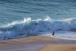
Wave overtopping is the time-averaged amount of water that is discharged per linear metre by waves over a structure such as a breakwater, revetment or dike which has a crest height above still water level.
When waves break over a dike, it causes water to flow onto the land behind it. Excessive overtopping is undesirable because it can compromise the integrity of the structure or result in a safety hazard, particularly when the structure is in an area where people, infrastructure or vehicles are present, such as in the case of a dike fronting an esplanade or densely populated area.
Wave overtopping typically transpires during extreme weather events, such as intense storms, which often elevate water levels beyond average due to wind setup. These effects may be further intensified when the storm coincides with a high spring tide.
Excessive overtopping may cause damage to the inner slope of the dike, potentially leading to failure and inundation of the land behind the dike, or create water-related issues on the inside of the dike due to excess water pressure and inadequate drainage. The amount of overtopping depends on factors including the freeboard, wave height, wave period, and slope of the dike.[1]
Overtopping factors and influences
Overtopping can transpire through various combinations of water levels and wave heights, wherein a low water level accompanied by high waves may yield an equivalent overtopping outcome to that of a higher water level with lower waves. This phenomenon is inconsequential when water levels and wave heights exhibit correlation; however, it poses difficulties in river systems where these factors are uncorrelated. In such instances, a probabilistic calculation is necessary.
The freeboard is the height of the dike's crest above the still water level, which usually corresponds to the determining storm surge level or river water level. Overtopping is typically expressed in litres per second per metre of dike length (L/s/m), as an average value. Overtopping follows the cyclical nature of waves, resulting in a large amount of water flowing over a structure, followed by a period with no water. The official website of the EurOtop Manual, which is widely used in the design of coastal engineering structures, features a number of visualisations of wave overtopping.[2][3][4][5]
In the case of overtopping at rubble-mound breakwaters, recent research using numerical models indicates that overtopping is strongly dependent on the slope angle.[6] Since present design guidelines for non-breaking waves do not include the effect of the slope angle, modified guidelines have also been proposed. Whilst these observed slope effects are too large to be ignored, they still need to be verified by tests using physical models.[6][7]
Overtopping behaviour is also influenced by the geometry and layout of different coastal structures. For example, seawalls (which are typically vertical, or near-vertical, as opposed to sloping breakwaters or revetments), are often situated behind natural beaches. Scour at the base of these structures during storms can have a direct impact on wave energy dissipation along their frontage, thus influencing wave overtopping. This phenomenon assumes critical importance when storms occur in such quick succession that the beach doesn't have sufficient time for sediments removed by the storm to be re-established. Experimental results show that, for near-vertical structures at the back of a beach, there is an increase in wave overtopping volume for a storm that starts from an eroded beach configuration, rather than a simple slope.[8]
Calculation of overtopping
This graph shows some of the results from laboratory experiments by Goda, Kishira and Kamiyama in 1975, in which scale model (vertical) sea walls were subject to overtopping. The graph shows the overtopping volume on the y axis, the crest height of the experimental structure on the x axis, and different experimental water depths are colour coded. An increased water depth in front of the structure results in a higher volume of overtopping, whilst increasing the crest height reduces it. In these graphs, the overtopping is a function of water depth and wave period, however current practice in the EurOtop Manual is to use the wave height. Goda's findings are however equally valid, and Hendrik Lorentz found similar results during measurements for the Zuiderzee Works in the 1920s.
Wave overtopping predominantly depends on the respective heights of individual waves compared to the crest level of the coastal structure involved. This overtopping doesn't occur continuously; rather, it's a sporadic event that takes place when particularly high waves within a storm impact the structure.[3][11]
The extent of wave overtopping is quantified by the volume of water that overflows onto the adjacent land. This can be measured either as the volume of water per wave for each unit length of the seawall, or as the average rate of overtopped water volume per unit length during the storm wave period.[11]
Much research into overtopping has been carried out, ranging from laboratory experiments to full-scale testing and the use of simulators.[12][13][14][15][16][17][18] In 1971, Jurjen Battjes developed a theoretically accurate equation for determining the average overtopping.[19][20] However, the formula's complexity, involving error functions, has limited its widespread adoption in practical applications. Consequently, an alternative empirical relationship has been established:
in which is the dimensionless overtopping, and is the dimensionless freeboard:
in which:
is the water depth
is the freeboard
is the overtopping discharge (in m³/s)
is the significant wave height at the toe of the structure
is the deep water wavelength
is the inclination of the slope (of e.g. the breakwater or revetment)
The values of and depend on the type of breaking wave, as shown in the table below:
Type of wave
Value for
Value for
breaking (plunging)
0.067
4.3
non-breaking (surging)
0.2
2.3
Types of breaking wave
The resistance term has a value between approximately 0.5 (for two layers of loosely dumped armourstone) and 1.0 (for a smooth slope). The effect of a berm and obliquely incident waves is also taken into account through the resistance term. This is determined in the same way as when calculating wave run-up. Special revetment blocks that reduce wave run-up (e.g., Hillblock, Quattroblock) also reduce wave overtopping.[21][22] Since the governing overtopping is the boundary condition, this means that the use of such elements allows for a slightly lower flood barrier.[23]
Research for the EurOtop manual has provided much additional data, and based on this, the formula has been slightly modified to:
with a maximum of:
It turns out that this formula is also a perfect rational approximation of the original Battjes formula.
In certain applications, it may also be necessary to calculate individual overtopping quantities, i.e. the overtopping per wave. The volumes of individual overtopping waves are Weibull distributed. The overtopping volume per wave for a given probability of exceedance is given by:
in which is the probability of exceedance of the calculated volume, is the probability of overtopping waves, and is the crest height.[24][25]
Calculation and measurement of overtopping at rock revetment crests
In terms of revetments, the overtopping discussed in the EurOtop manual refers to the overtopping measured at the seaward edge of the revetment crest.[4] The formulas above describe the wave overtopping occurring at the sea-side edge of the crest. In scenarios where the crest is impermeable (for example, a road surface or a clay layer), the volume of water overtopping the inland side of the crest would roughly equal that on the seaside. However, in the case of a rock armour breakwater with a more permeable crest, a large part of the overtopping water will seep into the crest, thus providing less overtopping on the inside of it. To analyse this effect, reduction coefficient can be used. This factor can be multiplied by 0.5 for a standard crest, with a width of about three rocks. This can result in a significant reduction in overtopping, and thus in the required crest height. If, behind the crest at a lower level, a permeable rock armour layer is installed with width , the amount of overtopping on the landside of this layer decreases still further. In that case, the reduction term (not to be confused with the reduction co-efficient ) can be multiplied by , in which is the crest width.[26][27][28]
Berm breakwaters
The circumstances surrounding overtopping at berm-type breakwaters differ slightly from those of dikes. Minor wave overtopping may occur as splashes from waves striking individual rocks. However, significant overtopping typically results in a horizontal flow across the crest, similar to what happens with dikes. The primary distinction lies in the wave heights used for designing these structures. Dikes rarely face wave heights exceeding 3 metres, while berm breakwaters are often designed to withstand wave heights of around 5 metres. This difference impacts the overtopping behaviour when dealing with smaller overtopping discharges.[29]
Tolerable overtopping
Traditionally, permissible average overtopping discharge has been utilised as a standard for designing coastal structures. It is necessary to restrict the average overtopping discharge to guarantee both the structural integrity of the structure, as well as the protection of individuals, vehicles, and properties situated behind it. Design handbooks often stipulate the thresholds for the maximum individual overtopping volumes, necessitating the examination of wave overtopping on a wave-per-wave basis. Often, to ensure a more dependable level of safety for pedestrians and vehicles, or to evaluate the stability of the inner slope of a revetment, it is necessary to consider the peak velocity and thickness of the overtopping flow.[30]
The tolerable overtopping is the overtopping which the design accepts may occur during a design storm condition. It is dependent on a number of factors including the intended use of the dike or coastal structure, and the quality of the revetment. Tolerable overtopping volumes are site-specific and depend on various factors, including the size and usage of the receiving area, the dimensions and capacity of drainage ditches, damage versus inundation curves, and return period. For coastal defences safeguarding the lives and well-being of residents, workers, and recreational users, designers and overseeing authorities must also address the direct hazards posed by overtopping. This necessitates evaluating the level of hazard and its likelihood of occurrence, thereby enabling the development of suitable action plans to mitigate risks associated with overtopping events.[4]
For rubble mound breakwaters (e.g., in harbour breakwaters) and a significant wave height greater than 5m on the outside, a heavy rubble mound revetment on the inside is required for overtopping of 10-30 L/s per metre. For overtopping of 5-20 L/s per metre, there is a high risk of damage to the crest.
Situation on the slope
(L/s per metre)
Quarry stone in waves > 5m, and some damage
1
Quarry stone in waves > 5m, and some damage(*)
5 - 10
Good grass cover between 1m and 3m
5
Poor grass cover between 0.5m and 3m
0.1
Poor grass cover < 1m
5 - 10
Poor grass cover < 0.3 m
Unlimited
(*)and inner slope designed for overtopping
For regular grass, an average overtopping of 5 L/s per metre of dike is considered permissible. For very good grass cover, without special elements or street furniture such as stairs, sign poles, or fences, 10 L/s per metre is allowed. Overtopping tests with a wave overtopping simulator have shown that for an undamaged grass cover, without special elements, 50L/s per metre often causes no damage. The problem is not so much the strength of the grass cover, but the presence of other elements such as gates, stairs and fences. It should be considered that, for example, 5 L/s per metre can occur due to high waves and a high freeboard, or low waves with a low freeboard. In the first case, there are not many overtopping waves, but when one overtops, it creates a high flow velocity on the inner slope. In the second case, there are many overtopping waves, but they create relatively low flow velocities. As a result, the requirements for overtopping over river dikes are different from those for sea dikes.[26]
A good sea dike with a continuous grass cover can easily handle 10 L/s per metre without problems, assuming good drainage is provided at the foot of the inner slope. Without adequate drainage, the amount of water that could potentially enter properties at the foot of the inner slope would be unacceptable, which is why such dikes are designed for a lower overtopping amount. Since it has been found that a grass cover does not fail due to the average overtopping, but rather due to the frequent occurrence of high flow velocities, coastal authorities such as Rijkswaterstaat in the Netherlands have decided (since 2015) to no longer test grass slopes on the inner side of the dike for average overtopping discharge, but rather for the frequency of high flow velocities during overtopping.[31][32]
Research has shown that grass roots can contribute to improving the shear strength of soil used in dike construction, providing that the grass is properly maintained.[33] Developing a grass cover takes time and requires a suitable substrate, such as lean and reasonably compacted clay. Firmly compacted clay soil is initially unsuitable for colonisation by grass plants. However, after a frost or winter period, the top layer of such a compacted clay layer is sufficiently open for the establishment of grass. To function properly, grass cover formation must begin well before winter.[34]
Research in The Netherlands has found that dikes with a well-compacted and flat clay lining can withstand a limited wave height or limited wave overtopping, such as in the majority of river areas, during the first winter after construction even without a grass cover, for many days without significant damage. If the wave load in the river area is higher, no damage that threatens safety will occur if the clay lining is thick enough (0.8 metres or more) and adequately compacted throughout its entire thickness. An immature grass cover can be temporarily protected against hydraulic loads with stapled geotextile mats.[35]
Category
(m)
L/s per metre
Pedestrians with a view of the sea
3
0.3
Pedestrians with a view of the sea
2
1
Pedestrians with a view of the sea
1
10-20
Pedestrians with a view of the sea
<0.5
Unlimited
Cars, trains
3
<5
Cars, trains
2
10-20
Cars, trains
1
<75
For damage to ships in harbours or marinas, the following figures can be used:
Category
(m)
L/s per metre
Sinking of large ships
>5
>10
Sinking of large ships
3 - 5
>20
Damage to small ships
3 - 5
>5
Safe for large ships
> 5
<5
Safe for small ships
3- 5
<1
Damage to buildings
1-3
<1
Damage to equipment and street furniture
<1
These values provide guidance on the expected impact of overtopping on ships in marinas or harbours, on nearby buildings and other infrastructure, depending on the significant wave height and overtopping rate (in L/s per metre). This information then helps to inform the appropriate design, the required protection measures, and response plans for different scenarios.[24]
Wave transmission
A dike at Den HelderSimulation of overtopping on the inner slope of the IJsseldijk in Zwolle
When there is water on both sides of a barrier (such as in the case of a harbour dam, breakwater or closure dam), wave overtopping over the dam will also generate waves on the other side of the dam. This is called wave transmission. To determine the amount of wave transmission, it is not necessary to determine the amount of overtopping. The transmission depends only on the wave height on the outer side, the freeboard, and the roughness of the slope. For a smooth slope, the transmission coefficient (the relationship between the wave on the inside of the dam and the incoming wave) is:
In which ξ0p is the Iribarren number based on the peak period of the waves, and β is the angle of incidence of the waves.[36][24]
Overtopping simulation
In order to assess the safety and resilience of dikes, as well as the robustness of the grass lining on their crests and landward slopes, a wave overtopping simulator can be employed. The most onerous wave conditions for which a dike is designed occur relatively rarely, so using a wave overtopping simulator enables in-situ replication of anticipated conditions on the dike itself. This allows the responsible organisation overseeing the structure to evaluate its capacity to withstand predicted wave overtopping during specific extreme scenarios.[37]
During these tests, the wave overtopping simulator is positioned on the dike's crest and continuously filled with water. The device features valves at its base that can be opened to release varying volumes of water, thereby simulating a wide range of wave overtopping events. This approach helps ensure that the dike's integrity is accurately and effectively assessed.[38]
In the case of dikes with grass slopes, another test method is to use a sod puller to determine the tensile strength of the sod, which can then be translated into strength under the load caused by wave overtopping. In addition to simulating wave overtopping, the simulation of wave impacts and wave run-up is possible with a specially developed generator and simulator.[39][40][24]
Grass dike erosion trials during overtopping, undertaken by Rijkswaterstaat in 1992
A levee, dike, dyke, embankment, floodbank, or stop bank is a structure used to keep the course of rivers from changing and to protect against flooding of the area adjoining the river or coast. It is usually earthen and often runs parallel to the course of a river in its floodplain or along low-lying coastlines.
The Smith chart, is a graphical calculator or nomogram designed for electrical and electronics engineers specializing in radio frequency (RF) engineering to assist in solving problems with transmission lines and matching circuits.
In fluid dynamics, a wind wave, or wind-generated water wave, is a surface wave that occurs on the free surface of bodies of water as a result of the wind blowing over the water's surface. The contact distance in the direction of the wind is known as the fetch. Waves in the oceans can travel thousands of kilometers before reaching land. Wind waves on Earth range in size from small ripples to waves over 30 m (100 ft) high, being limited by wind speed, duration, fetch, and water depth.
Wave power is the capture of energy of wind waves to do useful work – for example, electricity generation, water desalination, or pumping water. A machine that exploits wave power is a wave energy converter (WEC).
A Kelvin wave is a wave in the ocean or atmosphere that balances the Earth's Coriolis force against a topographic boundary such as a coastline, or a waveguide such as the equator. A feature of a Kelvin wave is that it is non-dispersive, i.e., the phase speed of the wave crests is equal to the group speed of the wave energy for all frequencies. This means that it retains its shape as it moves in the alongshore direction over time.
A breakwater is a permanent structure constructed at a coastal area to protect against tides, currents, waves, and storm surges. Breakwaters have been built since Antiquity to protect anchorages, helping isolate vessels from marine hazards such as wind-driven waves. A breakwater, also known in some contexts as a jetty or a Mole, may be connected to land or freestanding, and may contain a walkway or road for vehicle access.
A revetment in stream restoration, river engineering or coastal engineering is a facing of impact-resistant material applied to a bank or wall in order to absorb the energy of incoming water and protect it from erosion. River or coastal revetments are usually built to preserve the existing uses of the shoreline and to protect the slope.
Accropode blocks are wave-dissipating concrete blocks designed to resist the action of waves on breakwaters and coastal structures.
An Xbloc is a wave-dissipating concrete block designed to protect shores, harbour walls, seawalls, breakwaters and other coastal structures from the direct impact of incoming waves. The Xbloc model was designed and developed in 2001 by the Dutch firm Delta Marine Consultants, now called BAM Infraconsult, a subsidiary of the Royal BAM Group. Xbloc has been subjected to extensive research by several universities.
Beach evolution occurs at the shoreline where sea, lake or river water is eroding the land. Beaches exist where sand accumulated from centuries-old, recurrent processes that erode rocky and sedimentary material into sand deposits. River deltas deposit silt from upriver, accreting at the river's outlet to extend lake or ocean shorelines. Catastrophic events such as tsunamis, hurricanes, and storm surges accelerate beach erosion.
Hudson's equation, also known as Hudson formula, is an equation used by coastal engineers to calculate the minimum size of riprap (armourstone) required to provide satisfactory stability characteristics for rubble structures such as breakwaters under attack from storm wave conditions.
Coastal engineering is a branch of civil engineering concerned with the specific demands posed by constructing at or near the coast, as well as the development of the coast itself.
In fluid dynamics, the mild-slope equation describes the combined effects of diffraction and refraction for water waves propagating over bathymetry and due to lateral boundaries—like breakwaters and coastlines. It is an approximate model, deriving its name from being originally developed for wave propagation over mild slopes of the sea floor. The mild-slope equation is often used in coastal engineering to compute the wave-field changes near harbours and coasts.
In fluid dynamics, the Iribarren number or Iribarren parameter – also known as the surf similarity parameter and breaker parameter – is a dimensionless parameter used to model several effects of (breaking) surface gravity waves on beaches and coastal structures. The parameter is named after the Spanish engineer Ramón Iribarren Cavanilles (1900–1967), who introduced it to describe the occurrence of wave breaking on sloping beaches. The parameter used to describe breaking wave types on beaches; or wave run-up on – and reflection by – beaches, breakwaters and dikes.
Open channel spillways are dam spillways that utilize the principles of open-channel flow to convey impounded water in order to prevent dam failure. They can function as principal spillways, emergency spillways, or both. They can be located on the dam itself or on a natural grade in the vicinity of the dam.
The nonlinearity of surface gravity waves refers to their deviations from a sinusoidal shape. In the fields of physical oceanography and coastal engineering, the two categories of nonlinearity are skewness and asymmetry. Wave skewness and asymmetry occur when waves encounter an opposing current or a shallow area. As waves shoal in the nearshore zone, in addition to their wavelength and height changing, their asymmetry and skewness also change. Wave skewness and asymmetry are often implicated in ocean engineering and coastal engineering for the modelling of random sea states, in particular regarding the distribution of wave height, wavelength and crest length. For practical engineering purposes, it is important to know the probability of these wave characteristics in seas and oceans at a given place and time. This knowledge is crucial for the prediction of extreme waves, which are a danger for ships and offshore structures. Satellite altimeter Envisat RA-2 data shows geographically coherent skewness fields in the ocean and from the data has been concluded that large values of skewness occur primarily in regions of large significant wave height.
The Van der Meer formula is a formula for calculating the required stone weight for armourstone under the influence of (wind) waves. This is necessary for the design of breakwaters and shoreline protection. Around 1985 it was found that the Hudson formula in use at that time had considerable limitations. That is why the Dutch government agency Rijkswaterstaat commissioned Deltares to start research for a more complete formula. This research, conducted by Jentsje van der Meer, resulted in the Van der Meer formula in 1988, as described in his dissertation. This formula reads
Ramón Iribarren CavanillesIng.D was a Spanish Basque civil engineer and professor of ports at the School of Civil Engineering in Madrid. He was chairman of the Spanish delegation to the Permanent International Association of Navigation Congresses (PIANC) and was elected as an academic at the Spanish Royal Academy of Sciences, although he did not take up the latter position. He made notable contributions in the field of coastal engineering, including methods for the calculation of breakwater stability and research which led to the development of the Iribarren number.
Wave run-up is the height to which waves run up the slope of a revetment, bank or dike, regardless of whether the waves are breaking or not. Conversely, wave run-down is the height to which waves recede. These heights are always measured vertically. The wave run-up height, denoted by , , or , is a very important parameter in coastal engineering as, together with the design highest still water level, it determines the required crest height of a dike or revetment.
Yoshimi Goda was a Japanese civil engineer who made significant contributions to coastal engineering in Japan and internationally. He undertook a large volume of research on coastal engineering problems, and developed methods for the design of monolithic breakwaters.
↑ Lorentz, H.A.; Wortman, H.; van Everdingen, E.; Stoel, W.F.; Behrens, W.K.; de Blocq van Kuffeler, V.J.P.; Du Croix, W.K.; Gallé, P.H.; Gelinck, W.G.C.; Gockinga, R.H.; Kooper, J.; Lely, C.W.; Lumme, J.L.H.; Mansholt, L.H.; Mazure, J.P.; de Muralt, R.R.L.; de Nerée Tot Babberich, L.M.; Phaff, J.M.; Reigersman, C.J.A.; Thijsse, J.Th.; van der Stok, J.P.; van Loon, A.R.; van Vlissingen, J.P.; de Vries, J.J.; Wijtenhorst, J.P.; Wouda, D.F. (1926). Verslag van de commissie Lorentz (gevolgen afsluiting Zuiderzee op het getij)[Report of the Lorentz Committee (Effects of the closure of the Zuiderzee on the tide)] (in Dutch). The Hague: Staatsdrukkerij en -uitgeverijbedrijf. Retrieved 15 July 2023.
↑ Lioutas, A.C.; Smith, G.M.; Verhagen, H.J. (2012). Spatial distribution of overtopping. ICCE 2012: Proceedings of the 33rd International Conference on Coastal Engineering. Santander. Retrieved 13 April 2023.
↑ NL, WUR (14 September 2012). "Onderzoek Grasbekleding Dijken"[Research on grass coverings for dikes]. WUR (in Dutch). Retrieved 11 April 2023.
↑ Klein Breteler, M.; 't Hart, R.; Verheij, H. J.; Knoeff, H. (2010). "Reststerkte van dijken na initiële schade"[Residual strength of dikes after initial damage]. Rapport 1200393-002-HYE-0010 voor Waterdienst, Rijkswaterstaat.
This page is based on this Wikipedia article Text is available under the CC BY-SA 4.0 license; additional terms may apply. Images, videos and audio are available under their respective licenses.