This article needs additional citations for verification .(November 2013) (Learn how and when to remove this template message) |

A waveform monitor is a special type of oscilloscope used in television production applications. It is typically used to measure and display the level, or voltage, of a video signal with respect to time.

An oscilloscope, previously called an oscillograph, and informally known as a scope or o-scope, CRO, or DSO, is a type of electronic test instrument that graphically displays varying signal voltages, usually as a two-dimensional plot of one or more signals as a function of time. Other signals can be converted to voltages and displayed.

Voltage, electric potential difference, electric pressure or electric tension is the difference in electric potential between two points. The difference in electric potential between two points in a static electric field is defined as the work needed per unit of charge to move a test charge between the two points. In the International System of Units, the derived unit for voltage is named volt. In SI units, work per unit charge is expressed as joules per coulomb, where 1 volt = 1 joule per 1 coulomb. The official SI definition for volt uses power and current, where 1 volt = 1 watt per 1 ampere. This definition is equivalent to the more commonly used 'joules per coulomb'. Voltage or electric potential difference is denoted symbolically by ∆V, but more often simply as V, for instance in the context of Ohm's or Kirchhoff's circuit laws.

Time is the indefinite continued progress of existence and events that occur in apparently irreversible succession from the past, through the present, to the future. Time is a component quantity of various measurements used to sequence events, to compare the duration of events or the intervals between them, and to quantify rates of change of quantities in material reality or in the conscious experience. Time is often referred to as a fourth dimension, along with three spatial dimensions.
The level of a video signal usually corresponds to the brightness, or luminance, of the part of the image being drawn onto a regular video screen at the same point in time. A waveform monitor can be used to display the overall brightness of a television picture, or it can zoom in to show one or two individual lines of the video signal. It can also be used to visualize and observe special signals in the vertical blanking interval of a video signal, as well as the colorburst between each line of video.
In a raster graphics display, the vertical blanking interval (VBI), also known as the vertical interval or VBLANK, is the time between the end of the final line of a frame or field and the beginning of the first line of the next frame. It is present in analog television, VGA, DVI and other signals. During the VBI, the incoming data stream is not displayed on the screen. In raster cathode ray tube displays, the beam is blanked to avoid displaying the retrace line; see raster scan for details. The signal source, such as a television broadcast, does not supply image information during the blanking period.
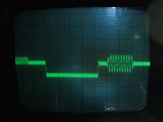
Colorburst is an analog video, composite video signal generated by a video-signal generator used to keep the chrominance subcarrier synchronized in a color television signal. By synchronizing an oscillator with the colorburst at the back porch (beginning) of each scan line, a television receiver is able to restore the suppressed carrier of the chrominance (color) signals, and in turn decode the color information. The most common use of colorburst is to genlock equipment together as a common reference with a vision mixer in a television studio using a multi-camera setup.
Waveform monitors are used for the following purposes:
- To assist with the calibration of professional video cameras, and to "line up" multiple-camera setups being used at the same location in order to ensure that the same scene shot under the same conditions will produce the same results.
- As a tool to assist in telecine (film-to-tape transfer), color correction, and other video production activities
- To monitor video signals to make sure that neither the color gamut, nor the analog transmission limits, are violated.
- To diagnose and troubleshoot a television studio, or the equipment located therein.
- To assist with installation of equipment into a television facility, or with the commissioning or certification of a facility.
- In manufacturing test and research and development applications.
- For setting camera exposure in the case of video and digital cinema cameras.

A professional video camera is a high-end device for creating electronic moving images. Originally developed for use in television studios, they are now also used for music videos, direct-to-video movies, corporate and educational videos, marriage videos etc. Since the 2010s, most of the professional video cameras are digital professional video cameras.
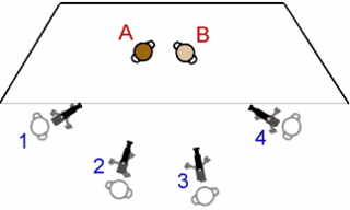
The multiple-camera setup, multiple-camera mode of production, multi-camera or simply multicam is a method of filmmaking and video production. Several cameras—either film or professional video cameras—are employed on the set and simultaneously record or broadcast a scene. It is often contrasted with single-camera setup, which uses one camera.

Telecine is the process of transferring motion picture film into video and is performed in a color suite. The term is also used to refer to the equipment used in the post-production process. Telecine enables a motion picture, captured originally on film stock, to be viewed with standard video equipment, such as television sets, video cassette recorders (VCR), DVD, Blu-ray Disc or computers. Initially, this allowed television broadcasters to produce programmes using film, usually 16mm stock, but transmit them in the same format, and quality, as other forms of television production. Furthermore, telecine allows film producers, television producers and film distributors working in the film industry to release their products on video and allows producers to use video production equipment to complete their filmmaking projects. Within the film industry, it is also referred to as a TK, because TC is already used to designate timecode.
A waveform monitor is often used in conjunction with a vectorscope. Originally, these were separate devices; however modern waveform monitors include vectorscope functionality as a separate mode. (The combined device is simply called a "waveform monitor").

A vectorscope is a special type of oscilloscope used in both audio and video applications. Whereas an oscilloscope or waveform monitor normally displays a plot of signal vs. time, a vectorscope displays an X-Y plot of two signals, which can reveal details about the relationship between these two signals. Vectorscopes are highly similar in operation to oscilloscopes operated in X-Y mode; however those used in video applications have specialized graticules, and accept standard television or video signals as input.
Originally, waveform monitors were entirely analog devices; the incoming (analog) video signal was filtered and amplified, and the resulting voltage was used to drive the vertical axis of a cathode ray tube. A sync stripper circuit was used to isolate the sync pulses and colorburst from the video signal; the recovered sync information was fed to a sweep circuit which drove the horizontal axis. Early waveform monitors differed little from oscilloscopes, except for the specialized video trigger circuitry. Waveform monitors also permit the use of external reference; in this mode the sync and burst signals are taken from a separate input (thus allowing all devices in a facility to be genlocked, or synchronized to the same timing source).
With the advent of digital television and digital signal processing, the waveform monitor acquired many new features and capabilities. Modern waveform monitors contain many additional modes of operation, including picture mode (where the video picture is simply presented on the screen, much like a television), various modes optimized for color gamut checking, support for the audio portion of a television program (either embedded with the video, or on separate inputs), eye pattern and jitter displays for measuring the physical layer parameters of serial-digital television formats, modes for examining the serial digital protocol layer, and support for ancillary data and television-related metadata such as timecode, closed captions and the v-chip rating systems.
Digital television (DTV) is the transmission of television signals, including the sound channel, using digital encoding, in contrast to the earlier television technology, analog television, in which the video and audio are carried by analog signals. It is an innovative advance that represents the first significant evolution in television technology since color television in the 1950s. Digital TV transmits in a new image format called HDTV, with greater resolution than analog TV, in a wide screen aspect ratio similar to recent movies in contrast to the narrower screen of analog TV. It makes more economical use of scarce radio spectrum space; it can transmit multiple channels, up to 7, in the same bandwidth occupied by a single channel of analog television, and provides many new features that analog television cannot. A transition from analog to digital broadcasting began around 2006 in some countries, and many industrial countries have now completed the changeover, while other countries are in various stages of adaptation. Different digital television broadcasting standards have been adopted in different parts of the world; below are the more widely used standards:
Digital signal processing (DSP) is the use of digital processing, such as by computers or more specialized digital signal processors, to perform a wide variety of signal processing operations. The signals processed in this manner are a sequence of numbers that represent samples of a continuous variable in a domain such as time, space, or frequency.
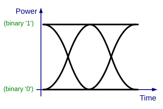
In telecommunication, an eye pattern, also known as an eye diagram, is an oscilloscope display in which a digital signal from a receiver is repetitively sampled and applied to the vertical input, while the data rate is used to trigger the horizontal sweep. It is so called because, for several types of coding, the pattern looks like a series of eyes between a pair of rails. It is a tool for the evaluation of the combined effects of channel noise and intersymbol interference on the performance of a baseband pulse-transmission system. It is the synchronised superposition of all possible realisations of the signal of interest viewed within a particular signaling interval.
Modern waveform monitors and other oscilloscopes have largely abandoned old-style CRT technology as well. All new waveform monitors are based on a rasterizer, a piece of graphics hardware that duplicates the behavior of a CRT vector display, generating a raster signal. They may come with a flat-panel liquid crystal display, or they may be sold without a display, in which case the user can connect any VGA display.