X-ray tube

Last updated
A modern dental X-ray tube. The heated cathode is on the left. Centre is the anode which is made from tungsten and embedded in the copper sleeve. Dental x-ray tube.jpg
A modern dental X-ray tube. The heated cathode is on the left. Centre is the anode which is made from tungsten and embedded in the copper sleeve.
William Coolidge explains medical imaging and X-rays.

An X-ray tube is a vacuum tube that converts electrical input power into X-rays. [1] The availability of this controllable source of X-rays created the field of radiography, the imaging of partly opaque objects with penetrating radiation. In contrast to other sources of ionizing radiation, X-rays are only produced as long as the X-ray tube is energized. X-ray tubes are also used in CT scanners, airport luggage scanners, X-ray crystallography, material and structure analysis, and for industrial inspection.

Contents

Increasing demand for high-performance Computed tomography (CT) scanning and angiography systems has driven development of very high performance medical X-ray tubes.

History

X-ray tubes evolved from experimental Crookes tubes with which X-rays were first discovered on November 8, 1895, by the German physicist Wilhelm Conrad Röntgen. The first-generation cold cathode or Crookes X-ray tubes were used until the 1920s. These tubes work by ionisation of residual gas within the tube. The positive ions bombard the cathode of the tube to release electrons, which are accelerated toward the anode and produce X-rays when they strike it. [2] The Crookes tube was improved by William Coolidge in 1913. [3] The Coolidge tube, also called a hot cathode tube, uses thermionic emission, where a tungsten cathode is heated to a sufficiently high temperature to emit electrons, which are then accelerated toward the anode in a near perfect vacuum. [2]

Until the late 1980s, X-ray generators were merely high-voltage, AC to DC variable power supplies. In the late 1980s a different method of control was emerging, called high speed switching. This followed the electronics technology of switching power supplies (aka switch mode power supply), and allowed for more accurate control of the X-ray unit, higher quality results and reduced X-ray exposures.[ citation needed ]

Physics

Spectrum of the X-rays emitted by an X-ray tube with a rhodium target, operated at 60 kV. The smooth, continuous curve is due to bremsstrahlung, and the spikes are characteristic K lines for rhodium atoms. Note that the emission starts around wavelength of 20pm corresponding to E=hc/l. TubeSpectrum.jpg
Spectrum of the X-rays emitted by an X-ray tube with a rhodium target, operated at 60 kV. The smooth, continuous curve is due to bremsstrahlung , and the spikes are characteristic K lines for rhodium atoms. Note that the emission starts around wavelength of 20pm corresponding to E=hc/λ.

As with any vacuum tube, there is a cathode, which emits electrons into the vacuum and an anode to collect the electrons, thus establishing a flow of electrical current, known as the beam, through the tube. A high voltage power source, for example 30 to 150 kilovolts (kV), called the tube voltage, is connected across cathode and anode to accelerate the electrons. The X-ray spectrum depends on the anode material and the accelerating voltage. [4]

Electrons from the cathode collide with the anode material, usually tungsten, molybdenum or copper, and accelerate other electrons, ions and nuclei within the anode material. About 1% of the energy generated is emitted/radiated, usually perpendicular to the path of the electron beam, as X-rays. The rest of the energy is released as heat. Over time, tungsten will be deposited from the target onto the interior surface of the tube, including the glass surface. This will slowly darken the tube and was thought to degrade the quality of the X-ray beam. Vaporized tungsten condenses on the inside of the envelope over the "window" and thus acts as an additional filter and decreases the tube's ability to radiate heat. [5] Eventually, the tungsten deposit may become sufficiently conductive that at high enough voltages, arcing occurs. The arc will jump from the cathode to the tungsten deposit, and then to the anode. This arcing causes an effect called "crazing" on the interior glass of the X-ray window. With time, the tube becomes unstable even at lower voltages, and must be replaced. At this point, the tube assembly (also called the "tube head") is removed from the X-ray system, and replaced with a new tube assembly. The old tube assembly is shipped to a company that reloads it with a new X-ray tube.

The two X-ray photon-generating effects are generally called the 'Characteristic effect' and the bremsstrahlung effect, a compound of the German bremsen meaning to brake, and Strahlung meaning radiation.

The range of photonic energies emitted by the system can be adjusted by changing the applied voltage, and installing aluminum filters of varying thicknesses. Aluminum filters are installed in the path of the X-ray beam to remove "soft" (non-penetrating) radiation. The number of emitted X-ray photons, or dose, are adjusted by controlling the current flow and exposure time.

Heat released

Heat is produced in the focal spot of the anode. Since a small fraction (less than or equal to 1%) of electron energy is converted to X-rays, it can be ignored in heat calculations. [6] The quantity of heat produced (in Joule) in the focal spot is given by :

being the waveform factor
= peak AC voltage (in Volts)
= tube current (in mili Amperes)
= exposure time (in seconds)

Heat Unit (HU) was used in the past as an alternative to Joule. It is a convenient unit when a single-phase power source is connected to the X-ray tube. [6] With a full-wave rectification of a sine wave, =, thus the heat unit:

1 HU = 0.707 J
1.4 HU = 1 J [7]

Types

Crookes tube (cold cathode tube)

Crookes X-ray tube from early 1900s. The cathode is on the right, the anode is in the center with attached heat sink at left. The electrode at the 10 o'clock position is the anticathode. The device at top is a 'softener' used to regulate the gas pressure. Cosser Crookes xray tube.jpg
Crookes X-ray tube from early 1900s. The cathode is on the right, the anode is in the center with attached heat sink at left. The electrode at the 10 o'clock position is the anticathode. The device at top is a 'softener' used to regulate the gas pressure.

Crookes tubes generated the electrons needed to create X-rays by ionization of the residual air in the tube, instead of a heated filament, so they were partially but not completely evacuated. They consisted of a glass bulb with around 10−6 to 5×10⁻⁸ atmospheric pressure of air (0.1 to 0.005 Pa). They had an aluminum cathode plate at one end of the tube, and a platinum anode target at the other end. The anode surface was angled so that the X-rays would radiate through the side of the tube. The cathode was concave so that the electrons were focused on a small (~1 mm) spot on the anode, approximating a point source of X-rays, which resulted in sharper images. The tube had a third electrode, an anticathode connected to the anode. It improved the X-ray output, but the method by which it achieved this is not understood. A more common arrangement used a copper plate anticathode (similar in construction to the cathode) in line with the anode such that the anode was between the cathode and the anticathode.

To operate, a DC voltage of a few kilovolts to as much as 100 kV was applied between the anodes and the cathode, usually generated by an induction coil, or for larger tubes, an electrostatic machine.

Crookes tubes were unreliable. As time passed, the residual air would be absorbed by the walls of the tube, reducing the pressure. This increased the voltage across the tube, generating 'harder' X-rays, until eventually the tube stopped working. To prevent this, 'softener' devices were used (see picture). A small tube attached to the side of the main tube contained a mica sleeve or chemical that released a small amount of gas when heated, restoring the correct pressure.

The glass envelope of the tube would blacken with usage due to the X-rays affecting its structure.

Coolidge tube (hot cathode tube)

Coolidge side-window tube (scheme)
C: filament/cathode (-)
A: anode (+)
Win and Wout: water inlet and outlet of the cooling device WaterCooledXrayTube.svg
Coolidge side-window tube (scheme)
  • C: filament/cathode (-)
  • A: anode (+)
  • Win and Wout: water inlet and outlet of the cooling device

In the Coolidge tube, the electrons are produced by thermionic effect from a tungsten filament heated by an electric current. The filament is the cathode of the tube. The high voltage potential is between the cathode and the anode, the electrons are thus accelerated, then hit the anode.

There are two designs: end-window tubes and side-window tubes. End window tubes usually have "transmission target" which is thin enough to allow X-rays to pass through the target (X-rays are emitted in the same direction as the electrons are moving.) In one common type of end-window tube, the filament is around the anode ("annular" or ring-shaped), the electrons have a curved path (half of a toroid).

What is special about side-window tubes is an electrostatic lens is used to focus the beam onto a very small spot on the anode. The anode is specially designed to dissipate the heat and wear resulting from this intense focused barrage of electrons. The anode is precisely angled at 1-20 degrees off perpendicular to the electron current to allow the escape of some of the X-ray photons which are emitted perpendicular to the direction of the electron current. The anode is usually made of tungsten or molybdenum. The tube has a window designed for escape of the generated X-ray photons.

The power of a Coolidge tube usually ranges from 0.1 to 18 kW.

Rotating anode tube

Simplified rotating anode tube schematic
A: Anode
C: cathode
T: Anode target
W: X-ray window Xraytubeinhousing commons.png
Simplified rotating anode tube schematic
  • A: Anode
  • C: cathode
  • T: Anode target
  • W: X-ray window
typical rotating anode X-ray tube Rotating anode x-ray tube (labeled).jpg
typical rotating anode X-ray tube

A considerable amount of heat is generated in the focal spot (the area where the beam of electrons coming from the cathode strike to) of a stationary anode. Rather, a rotating anode lets the electron beam sweep a larger area of the anode, thus redeeming the advantage of a higher intensity of emitted radiation, along with reduced damage to the anode compared to its stationary state. [8]

The focal spot temperature can reach 2,500 °C (4,530 °F) during an exposure, and the anode assembly can reach 1,000 °C (1,830 °F) following a series of large exposures. Typical anodes are a tungsten-rhenium target on a molybdenum core, backed with graphite. The rhenium makes the tungsten more ductile and resistant to wear from the impact of the electron beams. The molybdenum conducts heat from the target. The graphite provides thermal storage for the anode, and minimizes the rotating mass of the anode.

Microfocus X-ray tube

Some X-ray examinations (such as, e.g., non-destructive testing and 3-D microtomography) need very high-resolution images and therefore require X-ray tubes that can generate very small focal spot sizes, typically below 50 μm in diameter. These tubes are called microfocus X-ray tubes.

There are two basic types of microfocus X-ray tubes: solid-anode tubes and metal-jet-anode tubes.

Solid-anode microfocus X-ray tubes are in principle very similar to the Coolidge tube, but with the important distinction that care has been taken to be able to focus the electron beam into a very small spot on the anode. Many microfocus X-ray sources operate with focus spots in the range 5-20 μm, but in the extreme cases spots smaller than 1 μm may be produced.

The major drawback of solid-anode microfocus X-ray tubes is their very low operating power. To avoid melting the anode, the electron-beam power density must be below a maximum value. This value is somewhere in the range 0.4-0.8 W/μm depending on the anode material. [9] This means that a solid-anode microfocus source with a 10 μm electron-beam focus can operate at a power in the range 4-8 W.

In metal-jet-anode microfocus X-ray tubes the solid metal anode is replaced with a jet of liquid metal, which acts as the electron-beam target. The advantage of the metal-jet anode is that the maximum electron-beam power density is significantly increased. Values in the range 3-6 W/μm have been reported for different anode materials (gallium and tin). [10] [11] In the case with a 10 μm electron-beam focus a metal-jet-anode microfocus X-ray source may operate at 30-60 W.

The major benefit of the increased power density level for the metal-jet X-ray tube is the possibility to operate with a smaller focal spot, say 5 μm, to increase image resolution and at the same time acquire the image faster, since the power is higher (15-30 W) than for solid-anode tubes with 10 μm focal spots.

Hazards of X-ray production from vacuum tubes

Two high voltage rectifier tubes capable of producing X-rays Hvtubes.jpg
Two high voltage rectifier tubes capable of producing X-rays

Any vacuum tube operating at several thousand volts or more can produce X-rays as an unwanted byproduct, raising safety issues. [12] [13] The higher the voltage, the more penetrating the resulting radiation and the more the hazard. CRT displays, once common in color televisions and computer displays, operate at 3-40 kilovolts depending on size, [14] making them the main concern among household appliances. Historically, concern has focused less on the cathode ray tube, since its thick glass envelope is impregnated with several pounds of lead for shielding, than on high voltage (HV) rectifier and voltage regulator tubes inside earlier TVs. In the late 1960s it was found that a failure in the HV supply circuit of some General Electric TVs could leave excessive voltages on the regulator tube, causing it to emit X-rays. The models were recalled and the ensuing scandal caused the US agency responsible for regulating this hazard, the Center for Devices and Radiological Health of the Food and Drug Administration (FDA), to require that all TVs include circuits to prevent excessive voltages in the event of failure. [15] The hazard associated with excessive voltages was eliminated with the advent of all-solid-state TVs, which have no tubes other than the CRT. Since 1969, the FDA has limited TV X-ray emission to 0.5 mR (milliroentgen) per hour. As other screen technologies advanced, starting in the 1990s, the production of CRTs was slowly phased out. These other technologies, such as LED, LCD and OLED, are incapable of producing x-rays due to the lack of a high voltage transformer.

See also

Patents

Related Research Articles

<span class="mw-page-title-main">Cathode-ray tube</span> Vacuum tube often used to display images

A cathode-ray tube (CRT) is a vacuum tube containing one or more electron guns, which emit electron beams that are manipulated to display images on a phosphorescent screen. The images may represent electrical waveforms on an oscilloscope, a frame of video on an analog television set (TV), digital raster graphics on a computer monitor, or other phenomena like radar targets. A CRT in a TV is commonly called a picture tube. CRTs have also been used as memory devices, in which case the screen is not intended to be visible to an observer. The term cathode ray was used to describe electron beams when they were first discovered, before it was understood that what was emitted from the cathode was a beam of electrons.

<span class="mw-page-title-main">Cathode ray</span> Beam of electrons observed in vacuum tubes

Cathode rays or electron beams (e-beam) are streams of electrons observed in discharge tubes. If an evacuated glass tube is equipped with two electrodes and a voltage is applied, glass behind the positive electrode is observed to glow, due to electrons emitted from the cathode. They were first observed in 1859 by German physicist Julius Plücker and Johann Wilhelm Hittorf, and were named in 1876 by Eugen Goldstein Kathodenstrahlen, or cathode rays. In 1897, British physicist J. J. Thomson showed that cathode rays were composed of a previously unknown negatively charged particle, which was later named the electron. Cathode-ray tubes (CRTs) use a focused beam of electrons deflected by electric or magnetic fields to render an image on a screen.

<span class="mw-page-title-main">Cathode</span> Electrode where reduction takes place

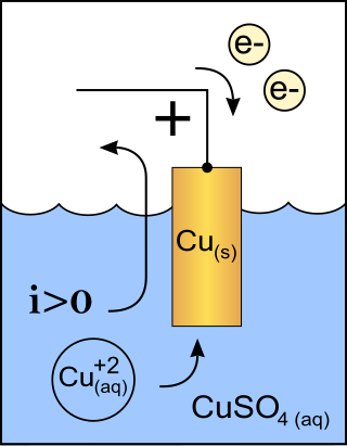
A cathode is the electrode from which a conventional current leaves a polarized electrical device. This definition can be recalled by using the mnemonic CCD for Cathode Current Departs. A conventional current describes the direction in which positive charges move. Electrons have a negative electrical charge, so the movement of electrons is opposite to that of the conventional current flow. Consequently, the mnemonic cathode current departs also means that electrons flow into the device's cathode from the external circuit. For example, the end of a household battery marked with a + (plus) is the cathode.

<span class="mw-page-title-main">Vacuum tube</span> Device that controls current between electrodes

A vacuum tube, electron tube, valve, or tube, is a device that controls electric current flow in a high vacuum between electrodes to which an electric potential difference has been applied.

<span class="mw-page-title-main">Geiger–Müller tube</span> Part of a Geiger counter

The Geiger–Müller tube or G–M tube is the sensing element of the Geiger counter instrument used for the detection of ionizing radiation. It is named after Hans Geiger, who invented the principle in 1908, and Walther Müller, who collaborated with Geiger in developing the technique further in 1928 to produce a practical tube that could detect a number of different radiation types.

<span class="mw-page-title-main">Cold cathode</span> Type of electrode and part of cold cathode fluorescent lamp.

A cold cathode is a cathode that is not electrically heated by a filament. A cathode may be considered "cold" if it emits more electrons than can be supplied by thermionic emission alone. It is used in gas-discharge lamps, such as neon lamps, discharge tubes, and some types of vacuum tube. The other type of cathode is a hot cathode, which is heated by electric current passing through a filament. A cold cathode does not necessarily operate at a low temperature: it is often heated to its operating temperature by other methods, such as the current passing from the cathode into the gas.

Space charge is an interpretation of a collection of electric charges in which excess electric charge is treated as a continuum of charge distributed over a region of space rather than distinct point-like charges. This model typically applies when charge carriers have been emitted from some region of a solid—the cloud of emitted carriers can form a space charge region if they are sufficiently spread out, or the charged atoms or molecules left behind in the solid can form a space charge region.

<span class="mw-page-title-main">X-ray machine</span> Machine that generates X-rays

An X-ray machine is a device that uses X-rays for a variety of applications including medicine, X-ray fluorescence, electronic assembly inspection, and measurement of material thickness in manufacturing operations. In medical applications, X-ray machines are used by radiographers to acquire x-ray images of the internal structures of living organisms, and also in sterilization.

<span class="mw-page-title-main">External beam radiotherapy</span> Treatment of cancer with ionized radiation

External beam radiation therapy (EBRT) is a form of radiotherapy that utilizes a high-energy collimated beam of ionizing radiation, from a source outside the body, to target and kill cancer cells. A radiotherapy beam is composed of particles which travel in a consistent direction; each radiotherapy beam consists of one type of particle intended for use in treatment, though most beams contain some contamination by other particle types.

<span class="mw-page-title-main">Electron gun</span> Electrical component producing a narrow electron beam

An electron gun is an electrical component in some vacuum tubes that produces a narrow, collimated electron beam that has a precise kinetic energy.

<span class="mw-page-title-main">Electron-beam welding</span> Use of electrons to join metal parts via melting

Electron-beam welding (EBW) is a fusion welding process in which a beam of high-velocity electrons is applied to two materials to be joined. The workpieces melt and flow together as the kinetic energy of the electrons is transformed into heat upon impact. EBW is often performed under vacuum conditions to prevent dissipation of the electron beam.

<span class="mw-page-title-main">Electron beam computed tomography</span> Medical diagnostic technology

Electron beam computed tomography (EBCT) is a specific form of computed tomography (CT) in which the X-ray tube is not mechanically spun in order to rotate the source of X-ray photons. This different design was explicitly developed to better image heart structures that never stop moving, performing a complete cycle of movement with each heartbeat.

A vacuum arc can arise when the surfaces of metal electrodes in contact with a good vacuum begin to emit electrons either through heating or in an electric field that is sufficient to cause field electron emission. Once initiated, a vacuum arc can persist, since the freed particles gain kinetic energy from the electric field, heating the metal surfaces through high-speed particle collisions. This process can create an incandescent cathode spot, which frees more particles, thereby sustaining the arc. At sufficiently high currents an incandescent anode spot may also be formed.

<span class="mw-page-title-main">Xenon arc lamp</span> Gas discharge lamp that produces intense white light

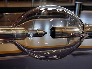
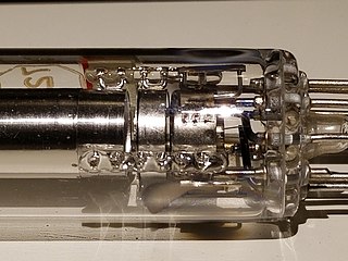
A xenon arc lamp is a highly specialized type of gas discharge lamp, an electric light that produces light by passing electricity through ionized xenon gas at high pressure. It produces a bright white light to simulate sunlight, with applications in movie projectors in theaters, in searchlights, and for specialized uses in industry and research. For instance, Xenon arc lamps with mercury lamps are the two most common lamps used in wide-field fluorescence microscopes.

<span class="mw-page-title-main">Crookes tube</span> Early type of cathode ray tube

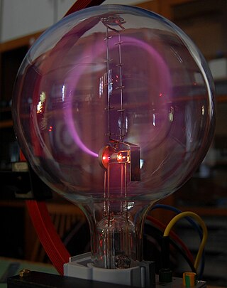
A Crookes tube is an early experimental electrical discharge tube, with partial vacuum, invented by English physicist William Crookes and others around 1869-1875, in which cathode rays, streams of electrons, were discovered.

<span class="mw-page-title-main">Teltron tube</span>

A teltron tube (named for Teltron Inc., which is now owned by 3B Scientific Ltd.) is a type of cathode ray tube used to demonstrate the properties of electrons. There were several different types made by Teltron including a diode, a triode, a Maltese Cross tube, a simple deflection tube with a fluorescent screen, and one which could be used to measure the charge-to-mass ratio of an electron. The latter two contained an electron gun with deflecting plates. The beams can be bent by applying voltages to various electrodes in the tube or by holding a magnet close by. The electron beams are visible as fine bluish lines. This is accomplished by filling the tube with low pressure helium (He) or Hydrogen (H2) gas. A few of the electrons in the beam collide with the helium atoms, causing them to fluoresce and emit light.

<span class="mw-page-title-main">Hot cathode</span> Type of electrode

In vacuum tubes and gas-filled tubes, a hot cathode or thermionic cathode is a cathode electrode which is heated to make it emit electrons due to thermionic emission. This is in contrast to a cold cathode, which does not have a heating element. The heating element is usually an electrical filament heated by a separate electric current passing through it. Hot cathodes typically achieve much higher power density than cold cathodes, emitting significantly more electrons from the same surface area. Cold cathodes rely on field electron emission or secondary electron emission from positive ion bombardment, and do not require heating. There are two types of hot cathode. In a directly heated cathode, the filament is the cathode and emits the electrons. In an indirectly heated cathode, the filament or heater heats a separate metal cathode electrode which emits the electrons.

<span class="mw-page-title-main">Wehnelt cylinder</span> Electrode in the electron gun assembly of some thermionic devices

A Wehnelt cylinder is an electrode in the electron gun assembly of some thermionic devices, used for focusing and control of the electron beam. It is named after Arthur Rudolph Berthold Wehnelt, a German physicist, who invented it during the years 1902 and 1903. Wehnelt cylinders are found in the electron guns of cathode ray tubes and electron microscopes, and in other applications where a thin, well-focused electron beam is required.

<span class="mw-page-title-main">Vircator</span>

A vircator is a microwave generator that is capable of generating brief pulses of tunable, narrow band microwaves at very high power levels. Its application is mainly in the area of electronic warfare, by way of interfering with electronic equipment such as radars or radio equipment.

References

  1. Behling, Rolf (2015). Modern Diagnostic X-Ray Sources, Technology, Manufacturing, Reliability. Boca Raton, FL, USA: Taylor and Francis, CRC Press. ISBN   9781482241327.
  2. 1 2 Mould, Richard F. (2017-12-29). "William David Coolidge (1873–1975). Biography with special reference to X-ray tubes". Nowotwory. Journal of Oncology. 67 (4): 273–280. doi: 10.5603/NJO.2017.0045 . ISSN   2300-2115.
  3. Coolidge, U.S. patent 1,203,495 . Priority date May 9, 1913.
  4. Diagram of continuum and characteristic lines Archived February 23, 2008, at the Wayback Machine
  5. John G. Stears; Joel P. Felmlee; Joel E. Gray (September 1986), "cf., Half-Value-Layer Increase Owing to Tungsten Buildup in the X-ray Tube: Fact or Fiction", Radiology, 160 (3): 837–838, doi:10.1148/radiology.160.3.3737925, PMID   3737925
  6. 1 2 Sprawls, Perry. "X-Ray Tube Heating and Cooling". The Physical Principles of Medical Imaging.
  7. Perry Sprawls, Ph.D. X-Ray Tube Heating and Cooling, from The web-based edition of The Physical Principles of Medical Imaging, 2nd Ed.
  8. "X-ray tube".
  9. D. E. Grider, A Wright, and P. K. Ausburn (1986), "Electron beam melting in microfocus x-ray tubes", J. Phys. D: Appl. Phys. 19: 2281-2292
  10. M. Otendal, T. Tuohimaa, U. Vogt, and H. M. Hertz (2008), "A 9 keV electron-impact liquid-gallium-jet x-ray source", Rev. Sci. Instrum. 79: 016102
  11. T. Tuohimaa, M. Otendal, and H. M. Hertz (2007), "Phase-contrast x-ray imaging with a liquid-metal-jet-anode microfocus source", Appl. Phys. Lett. 91: 074104
  12. "We want you to know about television radiation". Center for Devices and Radiological Health, US FDA. 2006. Archived from the original on December 18, 2007. Retrieved 2007-12-24.
  13. Pickering, Martin. "An informal history of X-ray protection". sci.electronics.repair FAQ. Archived from the original on 2012-02-07. Retrieved 2007-12-24.
  14. Hong, Michelle. "Voltage of a Television Picture Tube" . Retrieved 11 August 2016.
  15. Murray, Susan (2018-09-23). "When Televisions Were Radioactive". The Atlantic. Retrieved 2020-12-11.