
An ammeter is an instrument used to measure the current in a circuit. Electric currents are measured in amperes (A), hence the name. For direct measurement, the ammeter is connected in series with the circuit in which the current is to be measured. An ammeter usually has low resistance so that it does not cause a significant voltage drop in the circuit being measured.

An electric current is a flow of charged particles, such as electrons or ions, moving through an electrical conductor or space. It is defined as the net rate of flow of electric charge through a surface. The moving particles are called charge carriers, which may be one of several types of particles, depending on the conductor. In electric circuits the charge carriers are often electrons moving through a wire. In semiconductors they can be electrons or holes. In an electrolyte the charge carriers are ions, while in plasma, an ionized gas, they are ions and electrons.
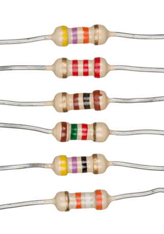
A resistor is a passive two-terminal electrical component that implements electrical resistance as a circuit element. In electronic circuits, resistors are used to reduce current flow, adjust signal levels, to divide voltages, bias active elements, and terminate transmission lines, among other uses. High-power resistors that can dissipate many watts of electrical power as heat may be used as part of motor controls, in power distribution systems, or as test loads for generators. Fixed resistors have resistances that only change slightly with temperature, time or operating voltage. Variable resistors can be used to adjust circuit elements, or as sensing devices for heat, light, humidity, force, or chemical activity.
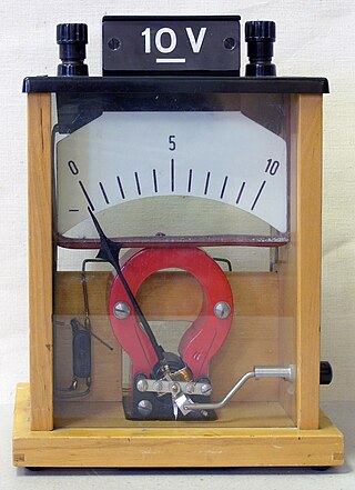
A voltmeter is an instrument used for measuring electric potential difference between two points in an electric circuit. It is connected in parallel. It usually has a high resistance so that it takes negligible current from the circuit.
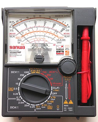
A multimeter is a measuring instrument that can measure multiple electrical properties. A typical multimeter can measure voltage, resistance, and current, in which case can be used as a voltmeter, ohmmeter, and ammeter. Some feature the measurement of additional properties such as temperature and capacitance.
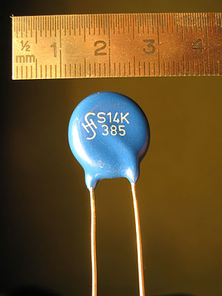
A varistor is a surge protecting electronic component with an electrical resistance that varies with the applied voltage. It has a nonlinear, non-ohmic current–voltage characteristic that is similar to that of a diode. Unlike a diode however, it has the same characteristic for both directions of traversing current. Traditionally, varistors were indeed constructed by connecting two rectifiers, such as the copper-oxide or germanium-oxide rectifier in antiparallel configuration. At low voltage the varistor has a high electrical resistance which decreases as the voltage is raised. Modern varistors are primarily based on sintered ceramic metal-oxide materials which exhibit directional behavior only on a microscopic scale. This type is commonly known as the metal-oxide varistor (MOV).

In electronics, a relaxation oscillator is a nonlinear electronic oscillator circuit that produces a nonsinusoidal repetitive output signal, such as a triangle wave or square wave. The circuit consists of a feedback loop containing a switching device such as a transistor, comparator, relay, op amp, or a negative resistance device like a tunnel diode, that repetitively charges a capacitor or inductor through a resistance until it reaches a threshold level, then discharges it again. The period of the oscillator depends on the time constant of the capacitor or inductor circuit. The active device switches abruptly between charging and discharging modes, and thus produces a discontinuously changing repetitive waveform. This contrasts with the other type of electronic oscillator, the harmonic or linear oscillator, which uses an amplifier with feedback to excite resonant oscillations in a resonator, producing a sine wave.

In electronics, negative resistance (NR) is a property of some electrical circuits and devices in which an increase in voltage across the device's terminals results in a decrease in electric current through it.

Electronic test equipment is used to create signals and capture responses from electronic devices under test (DUTs). In this way, the proper operation of the DUT can be proven or faults in the device can be traced. Use of electronic test equipment is essential to any serious work on electronics systems.

A Flexible Alternating Current Transmission System (FACTS) is a family of Power-Electronic based devices designed for use on an Alternating Current (AC) Transmission System to improve and control Power Flow and support Voltage. FACTs devices are alternatives to traditional electric grid solutions and improvements, where building additional Transmission Lines or Substation is not economically or logistically viable.

A DC motor is an electrical motor that uses direct current (DC) to produce mechanical force. The most common types rely on magnetic forces produced by currents in the coils. Nearly all types of DC motors have some internal mechanism, either electromechanical or electronic, to periodically change the direction of current in part of the motor.
A shunt is a device that is designed to provide a low-resistance path for an electrical current in a circuit. It is typically used to divert current away from a system or component in order to prevent overcurrent. Electrical shunts are commonly used in a variety of applications including power distribution systems, electrical measurement systems, automotive and marine applications.

A bifilar coil is an electromagnetic coil that contains two closely spaced, parallel windings. In electrical engineering, the word bifilar describes wire which is made of two filaments or strands. It is commonly used to denote special types of winding wire for transformers. Wire can be purchased in bifilar form, usually as different colored enameled wire bonded together. For three strands, the term trifilar coil is used.

A solenoid voltmeter is a specific type of voltmeter electricians use to test electrical power circuits. It uses a solenoid coil to attract a spring-loaded plunger; the movement of the plunger is calibrated in terms of approximate voltage. It is more rugged than a D'arsonval movement, but neither as sensitive nor as precise.
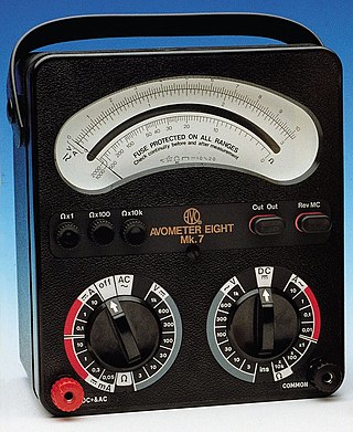
AVOmeter is a British trademark for a line of multimeters and electrical measuring instruments; the brand is now owned by the Megger Group Limited. The first Avometer was made by the Automatic Coil Winder and Electrical Equipment Co. in 1923, and measured direct voltage, direct current and resistance. Possibly the best known multimeter of the range was the Model 8, which was produced in various versions from May 1951 until 2008; the last version was the Mark 7.
A brushed DC electric motor is an internally commutated electric motor designed to be run from a direct current power source and utilizing an electric brush for contact.
A Kelvin bridge, also called a Kelvin double bridge and in some countries a Thomson bridge, is a measuring instrument used to measure unknown electrical resistors below 1 ohm. It is specifically designed to measure resistors that are constructed as four terminal resistors. Historically Kelvin bridges were used to measure shunt resistors for ammeters and sub one ohm reference resistors in metrology laboratories. In the scientific community the Kelvin bridge paired with a Null Detector was used to achieve the highest precision.

Guitar wiring refers to the electrical components, and interconnections thereof, inside an electric guitar. It most commonly consists of pickups, potentiometers to adjust volume and tone, a switch to select between different pickups, and the output socket. There may be additional controls for specific functions; the most common of these are described below.

The open-circuit test, or no-load test, is one of the methods used in electrical engineering to determine the no-load impedance in the excitation branch of a transformer. The no load is represented by the open circuit, which is represented on the right side of the figure as the "hole" or incomplete part of the circuit.
In electrical engineering, current sensing is any one of several techniques used to measure electric current. The measurement of current ranges from picoamps to tens of thousands of amperes. The selection of a current sensing method depends on requirements such as magnitude, accuracy, bandwidth, robustness, cost, isolation or size. The current value may be directly displayed by an instrument, or converted to digital form for use by a monitoring or control system.

