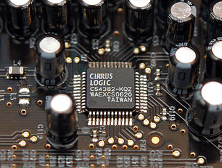
In electronics, an analog-to-digital converter is a system that converts an analog signal, such as a sound picked up by a microphone or light entering a digital camera, into a digital signal. An ADC may also provide an isolated measurement such as an electronic device that converts an input analog voltage or current to a digital number representing the magnitude of the voltage or current. Typically the digital output is a two's complement binary number that is proportional to the input, but there are other possibilities.

A high-voltage, direct current (HVDC) electric power transmission system uses direct current (DC) for the bulk transmission of electrical power, in contrast with the more common alternating current (AC) systems.

In electronics, a digital-to-analog converter is a system that converts a digital signal into an analog signal. An analog-to-digital converter (ADC) performs the reverse function.

A thyristor is a solid-state semiconductor device with four layers of alternating P- and N-type materials. It acts exclusively as a bistable switch, conducting when the gate receives a current trigger, and continuing to conduct until the voltage across the device is reversed biased, or until the voltage is removed. There are two designs, differing in what triggers the conducting state. In a three-lead thyristor, a small current on its Gate lead controls the larger current of the Anode to Cathode path. In a two-lead thyristor, conduction begins when the potential difference between the Anode and Cathode themselves is sufficiently large.

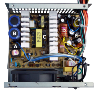
A switched-mode power supply is an electronic power supply that incorporates a switching regulator to convert electrical power efficiently. Like other power supplies, an SMPS transfers power from a DC or AC source to DC loads, such as a personal computer, while converting voltage and current characteristics. Unlike a linear power supply, the pass transistor of a switching-mode supply continually switches between low-dissipation, full-on and full-off states, and spends very little time in the high dissipation transitions, which minimizes wasted energy. A hypothetical ideal switched-mode power supply dissipates no power. Voltage regulation is achieved by varying the ratio of on-to-off time. In contrast, a linear power supply regulates the output voltage by continually dissipating power in the pass transistor. This higher power conversion efficiency is an important advantage of a switched-mode power supply. Switched-mode power supplies may also be substantially smaller and lighter than a linear supply due to the smaller transformer size and weight.

The Ćuk converter is a type of DC/DC converter that has an output voltage magnitude that is either greater than or less than the input voltage magnitude. It is essentially a boost converter followed by a buck converter with a capacitor to couple the energy.

In electronics, a sample and hold circuit is an analog device that samples the voltage of a continuously varying analog signal and holds its value at a constant level for a specified minimum period of time. Sample and hold circuits and related peak detectors are the elementary analog memory devices. They are typically used in analog-to-digital converters to eliminate variations in input signal that can corrupt the conversion process. They are also used in electronic music, for instance to impart a random quality to successively-played notes.
A DC-to-DC converter is an electronic circuit or electromechanical device that converts a source of direct current (DC) from one voltage level to another. It is a type of electric power converter. Power levels range from very low to very high.

Power electronics is the application of solid-state electronics to the control and conversion of electric power.

A charge pump is a kind of DC to DC converter that uses capacitors for energetic charge storage to raise or lower voltage. Charge-pump circuits are capable of high efficiencies, sometimes as high as 90–95%, while being electrically simple circuits.

A push–pull converter is a type of DC-to-DC converter, a switching converter that uses a transformer to change the voltage of a DC power supply. The distinguishing feature of a push-pull converter is that the transformer primary is supplied with current from the input line by pairs of transistors in a symmetrical push-pull circuit. The transistors are alternately switched on and off, periodically reversing the current in the transformer. Therefore, current is drawn from the line during both halves of the switching cycle. This contrasts with buck-boost converters, in which the input current is supplied by a single transistor which is switched on and off, so current is only drawn from the line during half the switching cycle. During the other half the output power is supplied by energy stored in inductors or capacitors in the power supply. Push–pull converters have steadier input current, create less noise on the input line, and are more efficient in higher power applications.
A switched capacitor (SC) is an electronic circuit element implementing a filter. It works by moving charges into and out of capacitors when switches are opened and closed. Usually, non-overlapping signals are used to control the switches, so that not all switches are closed simultaneously. Filters implemented with these elements are termed "switched-capacitor filters", and depend only on the ratios between capacitances. This makes them much more suitable for use within integrated circuits, where accurately specified resistors and capacitors are not economical to construct.
The Vyborg HVDC scheme is a system of electricity transmission from the Russian power system to Finland, using high-voltage direct current. It consists of four 355 MVA (250 MW) back-to-back converter blocks, the first three of which were completed in the early 1980s and the last in January 2001. Much of the original converter equipment has been refurbished or modernised.

Power management integrated circuits are integrated circuits for power management. Although PMIC refers to a wide range of chips, most include several DC/DC converters or their control part. A PMIC is often included in battery-operated devices such as mobile phones and portable media players to decrease the amount of space required.

The Vienna Rectifier is a pulse-width modulation rectifier, invented in 1993 by Johann W. Kolar.
The Sparse Matrix Converter is an AC/AC converter which offers a reduced number of components, a low-complexity modulation scheme, and low realization effort. Invented in 2001 by Prof Johann W. Kolar , sparse matrix converters avoid the multi step commutation procedure of the conventional matrix converter, improving system reliability in industrial operations. Its principal application is in highly compact integrated AC drives.
A solid-state AC-to-AC converter converts an AC waveform to another AC waveform, where the output voltage and frequency can be set arbitrarily.

Battery balancing and battery redistribution refer to techniques that improve the available capacity of a battery pack with multiple cells and increase each cell's longevity. A battery balancer or battery regulator is an electrical device in a battery pack that performs battery balancing. Balancers are often found in lithium-ion battery packs for laptop computers, electrical vehicles. etc.
Most of the terms listed in Wikipedia glossaries are already defined and explained within Wikipedia itself. However, glossaries like this one are useful for looking up, comparing and reviewing large numbers of terms together. You can help enhance this page by adding new terms or writing definitions for existing ones.
A multi-level converter (MLC) is a method of generating high-voltage wave-forms from lower-voltage components. MLC origins go back over a hundred years, when in the 1880s, the advantages of DC long-distance transmission became evident.


