
A locomotive or engine is a rail transport vehicle that provides the motive power for a train. If a locomotive is capable of carrying a payload, it is usually rather referred to as a multiple unit, motor coach, railcar or power car; the use of these self-propelled vehicles is increasingly common for passenger trains, but rare for freight trains.

A train is a series of connected vehicles that run along a railway track and transport people or freight. Trains are typically pulled or pushed by locomotives, though some are self-propelled, such as multiple units. Passengers and cargo are carried in railroad cars, also known as wagons. Trains are designed to a certain gauge, or distance between rails. Most trains operate on steel tracks with steel wheels, the low friction of which makes them more efficient than other forms of transport.
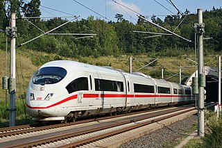
A multiple-unit train or simply multiple unit (MU) is a self-propelled train composed of one or more carriages joined, which when coupled to another multiple unit can be controlled by a single driver, with multiple-unit train control.
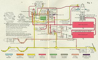
A railway air brake is a railway brake power braking system with compressed air as the operating medium. Modern trains rely upon a fail-safe air brake system that is based upon a design patented by George Westinghouse on April 13, 1869. The Westinghouse Air Brake Company was subsequently organized to manufacture and sell Westinghouse's invention. In various forms, it has been nearly universally adopted.

Brake van and guard's van are terms used mainly in the UK, Ireland, Australia and India for a railway vehicle equipped with a hand brake which can be applied by the guard. The equivalent North American term is caboose, but a British brake van and a caboose are very different in appearance, because the former usually has only four wheels, while the latter usually has bogies. German railways employed brakeman's cabins combined into other cars.

A diesel locomotive is a type of railway locomotive in which the power source is a diesel engine. Several types of diesel locomotives have been developed, differing mainly in the means by which mechanical power is conveyed to the driving wheels. The most common are diesel-electric locomotives and diesel-hydraulic.

An electric locomotive is a locomotive powered by electricity from overhead lines, a third rail or on-board energy storage such as a battery or a supercapacitor. Locomotives with on-board fuelled prime movers, such as diesel engines or gas turbines, are classed as diesel-electric or gas turbine-electric and not as electric locomotives, because the electric generator/motor combination serves only as a power transmission system.
In railway engineering, the term tractive effort describes the pulling or pushing capability of a locomotive. The published tractive force value for any vehicle may be theoretical—that is, calculated from known or implied mechanical properties—or obtained via testing under controlled conditions. The discussion herein covers the term's usage in mechanical applications in which the final stage of the power transmission system is one or more wheels in frictional contact with a railroad track.
Rail transport terms are a form of technical terminology applied to railways. Although many terms are uniform across different nations and companies, they are by no means universal, with differences often originating from parallel development of rail transport systems in different parts of the world, and in the national origins of the engineers and managers who built the inaugural rail infrastructure. An example is the term railroad, used in North America, and railway, generally used in English-speaking countries outside North America and by the International Union of Railways. In English-speaking countries outside the United Kingdom, a mixture of US and UK terms may exist.
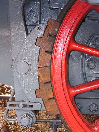
A railway brake is a type of brake used on the cars of railway trains to enable deceleration, control acceleration (downhill) or to keep them immobile when parked. While the basic principle is similar to that on road vehicle usage, operational features are more complex because of the need to control multiple linked carriages and to be effective on vehicles left without a prime mover. Clasp brakes are one type of brakes historically used on trains.

The British Rail Class 92 is a dual-voltage electric locomotive, which can run on 25 kV AC from overhead wires or 750 V DC from a third rail. It was designed specifically to operate services through the Channel Tunnel between Great Britain and France. Eurotunnel indicates the Class 92 locomotive as the reference for other locomotives which railway undertakings might want to get certified for usage in the Channel tunnel.

Rolling resistance, sometimes called rolling friction or rolling drag, is the force resisting the motion when a body rolls on a surface. It is mainly caused by non-elastic effects; that is, not all the energy needed for deformation of the wheel, roadbed, etc., is recovered when the pressure is removed. Two forms of this are hysteresis losses, and permanent (plastic) deformation of the object or the surface. Note that the slippage between the wheel and the surface also results in energy dissipation. Although some researchers have included this term in rolling resistance, some suggest that this dissipation term should be treated separately from rolling resistance because it is due to the applied torque to the wheel and the resultant slip between the wheel and ground, which is called slip loss or slip resistance. In addition, only the so-called slip resistance involves friction, therefore the name "rolling friction" is to an extent a misnomer.

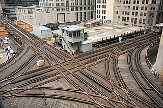
A rail yard, railway yard, railroad yard (US) or simply yard, is a series of tracks in a rail network for storing, sorting, or loading and unloading rail vehicles and locomotives. Yards have many tracks in parallel for keeping rolling stock or unused locomotives stored off the main line, so that they do not obstruct the flow of traffic. Cars or wagons are moved around by specially designed yard switcher locomotives (US) or shunter locomotives (UK), a type of locomotive. Cars or wagons in a yard may be sorted by numerous categories, including railway company, loaded or unloaded, destination, car type, or whether they need repairs. Yards are normally built where there is a need to store rail vehicles while they are not being loaded or unloaded, or are waiting to be assembled into trains. Large yards may have a tower to control operations.

An adhesion railway relies on adhesion traction to move the train, and is the most widespread and common type of railway in the world. Adhesion traction is the friction between the drive wheels and the steel rail. Since the vast majority of railways are adhesion railways, the term adhesion railway is used only when it is necessary to distinguish adhesion railways from railways moved by other means, such as by a stationary engine pulling on a cable attached to the cars or by railways that are moved by a pinion meshing with a rack.

Rail freight transport is the use of railroads and trains to transport cargo as opposed to human passengers.
Headway is the distance or duration between vehicles in a transit system measured in space or time. The minimum headway is the shortest such distance or time achievable by a system without a reduction in the speed of vehicles. The precise definition varies depending on the application, but it is most commonly measured as the distance from the tip of one vehicle to the tip of the next one behind it. It can be expressed as the distance between vehicles, or as time it will take for the trailing vehicle to cover that distance. A "shorter" headway signifies closer spacing between the vehicles. Airplanes operate with headways measured in hours or days, freight trains and commuter rail systems might have headways measured in parts of an hour, metro and light rail systems operate with headways on the order of 90 seconds to 20 minutes, and vehicles on a freeway can have as little as 2 seconds headway between them.
Electronically controlled pneumatic brakes are a type of railway braking systems.
The minimum railway curve radius is the shortest allowable design radius for the centerline of railway tracks under a particular set of conditions. It has an important bearing on construction costs and operating costs and, in combination with superelevation in the case of train tracks, determines the maximum safe speed of a curve. The minimum radius of a curve is one parameter in the design of railway vehicles as well as trams; monorails and automated guideways are also subject to a minimum radius.
Buffers and chain couplers are the de facto International Union of Railways (UIC) standard railway coupling used in the EU and UK, and on some surviving former colonial railways, such as in South America and India, on older rolling stock. Buffers and chain couplers are an assembly of several devices: buffers, hooks and links, or turnbuckle screws.

British Railways inherited a variety of brake vans from each of the Big Four: GWR, LNER, Southern Railway and LMS due to the nationalisation of the railways in 1948.


