
A rectifier is an electrical device that converts alternating current (AC), which periodically reverses direction, to direct current (DC), which flows in only one direction. The reverse operation is performed by an inverter.
In electrical engineering, electrical elements are conceptual abstractions representing idealized electrical components, such as resistors, capacitors, and inductors, used in the analysis of electrical networks. All electrical networks can be analyzed as multiple electrical elements interconnected by wires. Where the elements roughly correspond to real components, the representation can be in the form of a schematic diagram or circuit diagram. This is called a lumped-element circuit model. In other cases, infinitesimal elements are used to model the network in a distributed-element model.
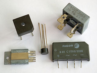
A diode bridge is a bridge rectifier circuit of four diodes that is used in the process of converting alternating current (AC) from the input terminals to direct current on the output terminals. Its function is to convert the negative voltage portions of the AC waveform to positive voltage, after which a low-pass filter can be used to smooth the result into DC.

A negative-feedback amplifier is an electronic amplifier that subtracts a fraction of its output from its input, so that negative feedback opposes the original signal. The applied negative feedback can improve its performance and reduces sensitivity to parameter variations due to manufacturing or environment. Because of these advantages, many amplifiers and control systems use negative feedback.

A power inverter, inverter, or invertor is a power electronic device or circuitry that changes direct current (DC) to alternating current (AC). The resulting AC frequency obtained depends on the particular device employed. Inverters do the opposite of rectifiers which were originally large electromechanical devices converting AC to DC.
In electronics, a linear regulator is a voltage regulator used to maintain a steady voltage. The resistance of the regulator varies in accordance with both the input voltage and the load, resulting in a constant voltage output. The regulating circuit varies its resistance, continuously adjusting a voltage divider network to maintain a constant output voltage and continually dissipating the difference between the input and regulated voltages as waste heat. By contrast, a switching regulator uses an active device that switches on and off to maintain an average value of output. Because the regulated voltage of a linear regulator must always be lower than input voltage, efficiency is limited and the input voltage must be high enough to always allow the active device to reduce the voltage by some amount.

In electronics, a common-base amplifier is one of three basic single-stage bipolar junction transistor (BJT) amplifier topologies, typically used as a current buffer or voltage amplifier.

An antenna tuner is a passive electronic device inserted between a radio transmitter and its antenna. Its purpose is to optimize power transfer by matching the impedance of the radio to the signal impedance on the feedline to the antenna.

A voltage regulator is a system designed to automatically maintain a constant voltage. It may use a simple feed-forward design or may include negative feedback. It may use an electromechanical mechanism, or electronic components. Depending on the design, it may be used to regulate one or more AC or DC voltages.
In an electrical system, a ground loop or earth loop occurs when two points of a circuit are intended to have the same ground reference potential but instead have a different potential between them. This is typically caused when enough current is flowing in the connection between the two ground points to produce a voltage drop and cause two points to be at different potentials. Current may be produced in a circular ground connection by electromagnetic induction.

In electrical engineering, an autotransformer is an electrical transformer with only one winding. The "auto" prefix refers to the single coil acting alone. In an autotransformer, portions of the same winding act as both the primary winding and secondary winding sides of the transformer. In contrast, an ordinary transformer has separate primary and secondary windings that are not connected by an electrically conductive path. between them.
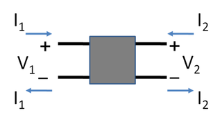
In electronics, a two-port network is an electrical network or device with two pairs of terminals to connect to external circuits. Two terminals constitute a port if the currents applied to them satisfy the essential requirement known as the port condition: the current entering one terminal must equal the current emerging from the other terminal on the same port. The ports constitute interfaces where the network connects to other networks, the points where signals are applied or outputs are taken. In a two-port network, often port 1 is considered the input port and port 2 is considered the output port.

The Cockcroft–Walton (CW) generator, or multiplier, is an electric circuit that generates a high DC voltage from a low-voltage AC or pulsing DC input. It was named after the British and Irish physicists John Douglas Cockcroft and Ernest Thomas Sinton Walton, who in 1932 used this circuit design to power their particle accelerator, performing the first artificial nuclear disintegration in history. They used this voltage multiplier cascade for most of their research, which in 1951 won them the Nobel Prize in Physics for "Transmutation of atomic nuclei by artificially accelerated atomic particles".

A tap changer is a mechanism in transformers which allows for variable turn ratios to be selected in distinct steps. This is done by connecting to a number of access points known as taps along either the primary or secondary winding.

A test probe is a physical device used to connect electronic test equipment to a device under test (DUT). Test probes range from very simple, robust devices to complex probes that are sophisticated, expensive, and fragile. Specific types include test prods, oscilloscope probes and current probes. A test probe is often supplied as a test lead, which includes the probe, cable and terminating connector.

A variety of types of electrical transformer are made for different purposes. Despite their design differences, the various types employ the same basic principle as discovered in 1831 by Michael Faraday, and share several key functional parts.
The circuit topology of an electronic circuit is the form taken by the network of interconnections of the circuit components. Different specific values or ratings of the components are regarded as being the same topology. Topology is not concerned with the physical layout of components in a circuit, nor with their positions on a circuit diagram; similarly to the mathematical concept of topology, it is only concerned with what connections exist between the components. There may be numerous physical layouts and circuit diagrams that all amount to the same topology.
An equivalent impedance is an equivalent circuit of an electrical network of impedance elements which presents the same impedance between all pairs of terminals as did the given network. This article describes mathematical transformations between some passive, linear impedance networks commonly found in electronic circuits.
Automatic test system switching test equipment allows for high-speed testing of a device or devices in a test situation, where strict sequences and combinations of switching must be observed. By automating the process in this way, the possibility of test errors and inaccuracies is minimized, and only systematic errors would generally be encountered due to such as an incorrect programmed test condition. This eliminates error due to human factors and allows application of a standard test sequence repetitively. The design of a test system’s switching configuration is governed by the test specification, which is derived from the functional tests to be performed.
The Miller theorem refers to the process of creating equivalent circuits. It asserts that a floating impedance element, supplied by two voltage sources connected in series, may be split into two grounded elements with corresponding impedances. There is also a dual Miller theorem with regards to impedance supplied by two current sources connected in parallel. The two versions are based on the two Kirchhoff's circuit laws.

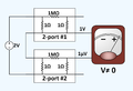 Brune Test Series-Series Failure.
 Brune test series-series pass with success obvious by inspection.
 Brune test series-series connection that passes because of transformer isolation.


