In fluid dynamics, the drag equation is a formula used to calculate the force of drag experienced by an object due to movement through a fully enclosing fluid. The equation is: where

In fluid dynamics, the drag coefficient is a dimensionless quantity that is used to quantify the drag or resistance of an object in a fluid environment, such as air or water. It is used in the drag equation in which a lower drag coefficient indicates the object will have less aerodynamic or hydrodynamic drag. The drag coefficient is always associated with a particular surface area.
Fluid bearings are bearings in which the load is supported by a thin layer of rapidly moving pressurized liquid or gas between the bearing surfaces. Since there is no contact between the moving parts, there is no sliding friction, allowing fluid bearings to have lower friction, wear and vibration than many other types of bearings. Thus, it is possible for some fluid bearings to have near-zero wear if operated correctly.
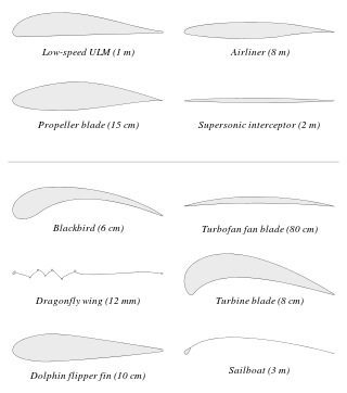
An airfoil or aerofoil is a streamlined body that is capable of generating significantly more lift than drag. Wings, sails and propeller blades are examples of airfoils. Foils of similar function designed with water as the working fluid are called hydrofoils.

Parasitic drag, also known as profile drag, is a type of aerodynamic drag that acts on any object when the object is moving through a fluid. Parasitic drag is a combination of form drag and skin friction drag. It affects all objects regardless of whether they are capable of generating lift.

A vortex ring, also called a toroidal vortex, is a torus-shaped vortex in a fluid; that is, a region where the fluid mostly spins around an imaginary axis line that forms a closed loop. The dominant flow in a vortex ring is said to be toroidal, more precisely poloidal.
In fluid dynamics, a Kármán vortex street is a repeating pattern of swirling vortices, caused by a process known as vortex shedding, which is responsible for the unsteady separation of flow of a fluid around blunt bodies.

Hydraulic machines use liquid fluid power to perform work. Heavy construction vehicles are a common example. In this type of machine, hydraulic fluid is pumped to various hydraulic motors and hydraulic cylinders throughout the machine and becomes pressurized according to the resistance present. The fluid is controlled directly or automatically by control valves and distributed through hoses, tubes, or pipes.

In fluid dynamics, vortex shedding is an oscillating flow that takes place when a fluid such as air or water flows past a bluff body at certain velocities, depending on the size and shape of the body. In this flow, vortices are created at the back of the body and detach periodically from either side of the body forming a Kármán vortex street. The fluid flow past the object creates alternating low-pressure vortices on the downstream side of the object. The object will tend to move toward the low-pressure zone.
In fluid dynamics, drag, sometimes referred to as fluid resistance, is a force acting opposite to the relative motion of any object moving with respect to a surrounding fluid. This can exist between two fluid layers, two solid surfaces, or between a fluid and a solid surface. Drag forces tend to decrease fluid velocity relative to the solid object in the fluid's path.

In fluid dynamics, vortex-induced vibrations (VIV) are motions induced on bodies interacting with an external fluid flow, produced by, or the motion producing, periodic irregularities on this flow.

In fluid dynamics, flow separation or boundary layer separation is the detachment of a boundary layer from a surface into a wake.

In fluid dynamics, the drag crisis is a phenomenon in which drag coefficient drops off suddenly as Reynolds number increases. This has been well studied for round bodies like spheres and cylinders. The drag coefficient of a sphere will change rapidly from about 0.5 to 0.2 at a Reynolds number in the range of 300000. This corresponds to the point where the flow pattern changes, leaving a narrower turbulent wake. The behavior is highly dependent on small differences in the condition of the surface of the sphere.
The Lanchester-Prandtl lifting-line theory is a mathematical model in aerodynamics that predicts lift distribution over a three-dimensional wing from the wing's geometry. The theory was expressed independently by Frederick W. Lanchester in 1907, and by Ludwig Prandtl in 1918–1919 after working with Albert Betz and Max Munk. In this model, the vortex bound to the wing develops along the whole wingspan because it is shed as a vortex-sheet from the trailing edge, rather than just as a single vortex from the wing-tips.

The Vortex lattice method, (VLM), is a numerical method used in computational fluid dynamics, mainly in the early stages of aircraft design and in aerodynamic education at university level. The VLM models the lifting surfaces, such as a wing, of an aircraft as an infinitely thin sheet of discrete vortices to compute lift and induced drag. The influence of the thickness and viscosity is neglected.

The primary application of wind turbines is to generate energy using the wind. Hence, the aerodynamics is a very important aspect of wind turbines. Like most machines, wind turbines come in many different types, all of them based on different energy extraction concepts.
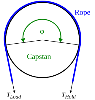
The capstan equation or belt friction equation, also known as Euler–Eytelwein formula, relates the hold-force to the load-force if a flexible line is wound around a cylinder.
In fluid dynamics the Morison equation is a semi-empirical equation for the inline force on a body in oscillatory flow. It is sometimes called the MOJS equation after all four authors—Morison, O'Brien, Johnson and Schaaf—of the 1950 paper in which the equation was introduced. The Morison equation is used to estimate the wave loads in the design of oil platforms and other offshore structures.
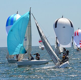
Forces on sails result from movement of air that interacts with sails and gives them motive power for sailing craft, including sailing ships, sailboats, windsurfers, ice boats, and sail-powered land vehicles. Similar principles in a rotating frame of reference apply to windmill sails and wind turbine blades, which are also wind-driven. They are differentiated from forces on wings, and propeller blades, the actions of which are not adjusted to the wind. Kites also power certain sailing craft, but do not employ a mast to support the airfoil and are beyond the scope of this article.

The dynamic stall is one of the hazardous phenomena on helicopter rotors, which can cause the onset of large torsional airloads and vibrations on the rotor blades. Unlike fixed-wing aircraft, of which the stall occurs at relatively low flight speed, the dynamic stall on a helicopter rotor emerges at high airspeeds or/and during manoeuvres with high load factors of helicopters, when the angle of attack(AOA) of blade elements varies intensively due to time-dependent blade flapping, cyclic pitch and wake inflow. For example, during forward flight at the velocity close to VNE, velocity, never exceed, the advancing and retreating blades almost reach their operation limits whereas flows are still attached to the blade surfaces. That is, the advancing blades operate at high Mach numbers so low values of AOA is needed but shock-induced flow separation may happen, while the retreating blade operates at much lower Mach numbers but the high values of AoA result in the stall.


