A machine is a physical system that uses power to apply forces and control movement to perform an action. The term is commonly applied to artificial devices, such as those employing engines or motors, but also to natural biological macromolecules, such as molecular machines. Machines can be driven by animals and people, by natural forces such as wind and water, and by chemical, thermal, or electrical power, and include a system of mechanisms that shape the actuator input to achieve a specific application of output forces and movement. They can also include computers and sensors that monitor performance and plan movement, often called mechanical systems.
Kinematics is a subfield of physics and mathematics, developed in classical mechanics, that describes the motion of points, bodies (objects), and systems of bodies without considering the forces that cause them to move. Kinematics, as a field of study, is often referred to as the "geometry of motion" and is occasionally seen as a branch of both applied and pure mathematics since it can be studied without considering the mass of a body or the forces acting upon it. A kinematics problem begins by describing the geometry of the system and declaring the initial conditions of any known values of position, velocity and/or acceleration of points within the system. Then, using arguments from geometry, the position, velocity and acceleration of any unknown parts of the system can be determined. The study of how forces act on bodies falls within kinetics, not kinematics. For further details, see analytical dynamics.

In kinematics, the parallel motion linkage is a six-bar mechanical linkage invented by the Scottish engineer James Watt in 1784 for the double-acting Watt steam engine. It allows a rod moving practically straight up and down to transmit motion to a beam moving in an arc, without putting significant sideways strain on the rod.
A Watt's linkage is a type of mechanical linkage invented by James Watt in which the central moving point of the linkage is constrained to travel a nearly straight path. Watt's described the linkage in his patent specification of 1784 for the Watt steam engine.
In the study of mechanisms, a four-bar linkage, also called a four-bar, is the simplest closed-chain movable linkage. It consists of four bodies, called bars or links, connected in a loop by four joints. Generally, the joints are configured so the links move in parallel planes, and the assembly is called a planar four-bar linkage. Spherical and spatial four-bar linkages also exist and are used in practice.
A mechanical linkage is an assembly of systems connected so as to manage forces and movement. The movement of a body, or link, is studied using geometry so the link is considered to be rigid. The connections between links are modeled as providing ideal movement, pure rotation or sliding for example, and are called joints. A linkage modeled as a network of rigid links and ideal joints is called a kinematic chain.
In physics, the degrees of freedom (DOF) of a mechanical system is the number of independent parameters that define its configuration or state. It is important in the analysis of systems of bodies in mechanical engineering, structural engineering, aerospace engineering, robotics, and other fields.
In mechanical engineering, an overconstrained mechanism is a linkage that has more degrees of freedom than is predicted by the mobility formula. The mobility formula evaluates the degree of freedom of a system of rigid bodies that results when constraints are imposed in the form of joints between the links.
In classical mechanics, a kinematic pair is a connection between two physical objects that imposes constraints on their relative movement (kinematics). German engineer Franz Reuleaux introduced the kinematic pair as a new approach to the study of machines that provided an advance over the notion of elements consisting of simple machines.

In mechanical engineering, a kinematic chain is an assembly of rigid bodies connected by joints to provide constrained motion that is the mathematical model for a mechanical system. As the word chain suggests, the rigid bodies, or links, are constrained by their connections to other links. An example is the simple open chain formed by links connected in series, like the usual chain, which is the kinematic model for a typical robot manipulator.
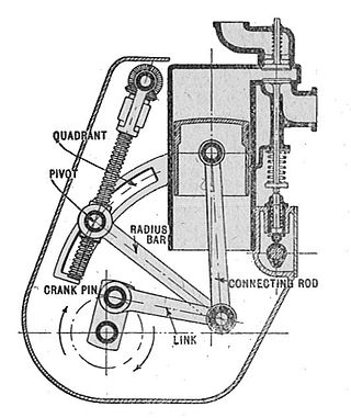
A straight-line mechanism is a mechanism that converts any type of rotary or angular motion to perfect or near-perfect straight-line motion, or vice versa. Straight-line motion is linear motion of definite length or "stroke", every forward stroke being followed by a return stroke, giving reciprocating motion. The first such mechanism, patented in 1784 by James Watt, produced approximate straight-line motion, referred to by Watt as parallel motion.

The Sarrus linkage, invented in 1853 by Pierre Frédéric Sarrus, is a mechanical linkage to convert a limited circular motion to a linear motion or vice versa without reference guideways. It is a spatial six-bar linkage (6R) with two groups of three parallel adjacent joint-axes.

In kinematics, cognate linkages are linkages that ensure the same coupler curve geometry or input-output relationship, while being dimensionally dissimilar. In case of four-bar linkage coupler cognates, the Roberts–Chebyshev Theorem, after Samuel Roberts and Pafnuty Chebyshev, states that each coupler curve can be generated by three different four-bar linkages. These four-bar linkages can be constructed using similar triangles and parallelograms, and the Cayley diagram.
The Chebychev–Grübler–Kutzbach criterion determines the number of degrees of freedom of a kinematic chain, that is, a coupling of rigid bodies by means of mechanical constraints. These devices are also called linkages.
The instant center of rotation of a body undergoing planar movement is a point that has zero velocity at a particular instant of time. At this instant, the velocity vectors of the other points in the body generate a circular field around this center of rotation which is identical to what is generated by a pure rotation.

In engineering, a mechanism is a device that transforms input forces and movement into a desired set of output forces and movement. Mechanisms generally consist of moving components which may include Gears and gear trains; Belts and chain drives; cams and followers; Linkages; Friction devices, such as brakes or clutches; Structural components such as a frame, fasteners, bearings, springs, or lubricants; Various machine elements, such as splines, pins, or keys.
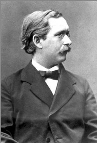
Ludwig Ernst Hans Burmester was a German kinematician and geometer.
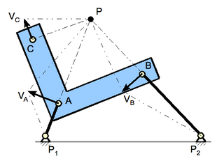
In kinematics, Burmester theory comprises geometric techniques for synthesis of linkages. It was introduced in the late 19th century by Ludwig Burmester (1840–1927). His approach was to compute the geometric constraints of the linkage directly from the inventor's desired movement for a floating link. From this point of view a four-bar linkage is a floating link that has two points constrained to lie on two circles.

Slider-crank chain inversion arises when the connecting rod, or coupler, of a slider-crank linkage becomes the ground link, so the slider is connected directly to the crank. This inverted slider-crank is the form of a slider-crank linkage that is often used to actuate a hinged joint in construction equipment like a crane or backhoe, as well as to open and close a swinging gate or door.
In mechanical engineering, kinematic synthesis determines the size and configuration of mechanisms that shape the flow of power through a mechanical system, or machine, to achieve a desired performance. The word synthesis refers to combining parts to form a whole. Hartenberg and Denavit describe kinematic synthesis as
...it is design, the creation of something new. Kinematically, it is the conversion of a motion idea into hardware.