Four-bar linkage

Last updated

In the study of mechanisms, a four-bar linkage, also called a four-bar, is the simplest closed-chain movable linkage. It consists of four bodies, called bars or links, connected in a loop by four joints. Generally, the joints are configured so the links move in parallel planes, and the assembly is called a planar four-bar linkage. Spherical and spatial four-bar linkages also exist and are used in practice. [1]

Contents

A pumpjack's main mechanism is a four-bar linkage Pump jack animation.gif
A pumpjack's main mechanism is a four-bar linkage

Planar four-bar linkage

Coupler curves of a crank-rocker four-bar linkage. Simulation done with MeKin2D. 4bar curves.gif
Coupler curves of a crank-rocker four-bar linkage. Simulation done with MeKin2D.
An example of an RRRP, or slider-crank, linkage. Crank Slider.gif
An example of an RRRP, or slider-crank, linkage.
An example of an RRPR, or inverted slider-crank, linkage. General crank-slider linkage.gif
An example of an RRPR, or inverted slider-crank, linkage.

Planar four-bar linkages are constructed from four links connected in a loop by four one-degree-of-freedom joints. A joint may be either a revolute joint – also known as a pin joint or hinged joint – denoted by R, or a prismatic joint – also known as a sliding pair – denoted by P. [Note 1]

A link that is fixed in place relative to the viewer is called a ground link.
A link connecting to the ground by a revolute joint that can perform a complete revolution is called a crank link.
A link connecting to the ground by a revolute joint that cannot perform a complete revolution is called a rocker link.
A link connecting to a ground line by a prismatic joint is called a slider. Sliders are sometimes considered to be cranks that have a hinged pivot at an infinitely long distance away perpendicular to the travel of the slider.
A link connecting to two other links is called a floating link or coupler. A coupler connecting a crank and a slider in a single slider crank mechanism is often called a connecting rod, however, it has also been used to refer to any type of coupler.

There are three basic types of planar four-bar linkage, depending on the use of revolute or prismatic joints:

  1. Four revolute joints:
    It is denoted as RRRR, constructed from four links connected by four revolute joints. The planar quadrilateral linkage refers to all arrangements in this type.
    Examples of 4R linkages include:
    • Double-crank linkage
    • Crank-rocker (Treadle) linkage (used in pumpjacks)
    • Double-rocker linkage (used in Ackermann steering)
    • Parallelogram (Parallel Motion [Note 2] ) and Antiparallelogram (Contraparallelogram, Inverse Parallelogram, Butterfly, Bow-tie) linkages
    • Deltoid (Galloway) and Trapezium (Arglin) linkages
  2. Three revolute joints:
    It is denoted as RRRP, PRRR, RPRR, or RRPR, constructed from four links connected by three revolute joints and one prismatic joint. The slider-crank linkage (RRRP) is one type of arrangement such that one link is a crank, which is then connected to a slider by a connecting rod. The inverted slider-crank is another type of arrangement such that there are two cranks with a slider acting as the coupler.
    Examples of 3R1P linkages include:
    • Single-slider crank mechanism (used in internal combustion engines)
    • Whitworth Quick Return mechanism (used in early types of shapers)
    • Crank and slotted lever Quick Return mechanism (used in shapers)
    • Fixed piston mechanism (used in hand pumps)
  3. Two revolute joints and two prismatic joints:
    It is denoted as PRRP, [2] and is constructed by connected two sliders with a coupler link. The doubler slider refers to all arrangements in this type.
    Examples of 2R2P linkages include:

Planar four-bar linkages can be designed to guide a wide variety of movements, and are often the base mechanisms found in many machines. Because of this, the kinematics and dynamics of planar four-bar linkages are also important topics in mechanical engineering.

Planar quadrilateral linkage

Planar quadrilateral linkage, RRRR or 4R linkages have four rotating joints. One link of the chain is usually fixed, and is called the ground link, fixed link, or the frame. The two links connected to the frame are called the grounded links and are generally the input and output links of the system, sometimes called the input link and output link. The last link is the floating link, which is also called a coupler or connecting rod because it connects an input to the output.

Assuming the frame is horizontal there are four possibilities for the input and output links: [2]

Some authors do not distinguish between the types of rocker.

Grashof condition

The Grashof condition for a four-bar linkage states: If the sum of the shortest and longest link of a planar quadrilateral linkage is less than or equal to the sum of the remaining two links, then the shortest link can rotate fully with respect to a neighboring link. In other words, the condition is satisfied if S + LP + Q, where S is the shortest link, L is the longest, and P and Q are the other links.

Classification

The movement of a quadrilateral linkage can be classified into eight cases based on the dimensions of its four links. Let a, b, g and h denote the lengths of the input crank, the output crank, the ground link and floating link, respectively. Then, we can construct the three terms:

;
;
.

The movement of a quadrilateral linkage can be classified into eight types based on the positive and negative values for these three terms, T1, T2, and T3. [2]

Grashof conditionInput linkOutput link
+GrashofCrankCrank
+++GrashofCrankRocker
+GrashofRockerCrank
+GrashofRockerRocker
Non-Grashof0-Rocker0-Rocker
++Non-Grashofπ-Rockerπ-Rocker
++Non-Grashofπ-Rocker0-Rocker
++Non-Grashof0-Rockerπ-Rocker

The cases of T1 = 0, T2 = 0, and T3 = 0 are interesting because the linkages fold. If we distinguish folding quadrilateral linkage, then there are 27 different cases. [3]

The figure shows examples of the various cases for a planar quadrilateral linkage. [4]

Grashof Type I Four-Bar Kinematic Inversions.gif
Types of four-bar linkages, s: shortest link, l: longest link. Linkage four bar fixed.svg
Types of four-bar linkages, s: shortest link, l: longest link.

The configuration of a quadrilateral linkage may be classified into three types: convex, concave, and crossing. In the convex and concave cases no two links cross over each other. In the crossing linkage two links cross over each other. In the convex case all four internal angles are less than 180 degrees, and in the concave configuration one internal angle is greater than 180 degrees. There exists a simple geometrical relationship between the lengths of the two diagonals of the quadrilateral. For convex and crossing linkages, the length of one diagonal increases if and only if the other decreases. On the other hand, for nonconvex non-crossing linkages, the opposite is the case; one diagonal increases if and only if the other also increases. [5]

Design of four-bar mechanisms

The synthesis, or design, of four-bar mechanisms is important when aiming to produce a desired output motion for a specific input motion. In order to minimize cost and maximize efficiency, a designer will choose the simplest mechanism possible to accomplish the desired motion. When selecting a mechanism type to be designed, link lengths must be determined by a process called dimensional synthesis. Dimensional synthesis involves an iterate-and-analyze methodology which in certain circumstances can be an inefficient process; however, in unique scenarios, exact and detailed procedures to design an accurate mechanism may not exist. [6]

Time ratio

The time ratio (Q) of a four-bar mechanism is a measure of its quick return and is defined as follows: [6]

With four-bar mechanisms there are two strokes, the forward and return, which when added together create a cycle. Each stroke may be identical or have different average speeds. The time ratio numerically defines how fast the forward stroke is compared to the quicker return stroke. The total cycle time (Δtcycle) for a mechanism is: [6]

Most four-bar mechanisms are driven by a rotational actuator, or crank, that requires a specific constant speed. This required speed (ωcrank)is related to the cycle time as follows: [6]

Some mechanisms that produce reciprocating, or repeating, motion are designed to produce symmetrical motion. That is, the forward stroke of the machine moves at the same pace as the return stroke. These mechanisms, which are often referred to as in-line design, usually do work in both directions, as they exert the same force in both directions. [6]

Examples of symmetrical motion mechanisms include:

Other applications require that the mechanism-to-be-designed has a faster average speed in one direction than the other. This category of mechanism is most desired for design when work is only required to operate in one direction. The speed at which this one stroke operates is also very important in certain machine applications. In general, the return and work-non-intensive stroke should be accomplished as fast as possible. This is so the majority of time in each cycle is allotted for the work-intensive stroke. These quick-return mechanisms are often referred to as offset. [6]

Examples of offset mechanisms include:

With offset mechanisms, it is very important to understand how and to what degree the offset affects the time ratio. To relate the geometry of a specific linkage to the timing of the stroke, an imbalance angle (β) is used. This angle is related to the time ratio, Q, as follows: [6]

Through simple algebraic rearrangement, this equation can be rewritten to solve for β: [6]

Timing charts

Timing charts are often used to synchronize the motion between two or more mechanisms. They graphically display information showing where and when each mechanism is stationary or performing its forward and return strokes. Timing charts allow designers to qualitatively describe the required kinematic behavior of a mechanism. [6]

These charts are also used to estimate the velocities and accelerations of certain four-bar links. The velocity of a link is the time rate at which its position is changing, while the link's acceleration is the time rate at which its velocity is changing. Both velocity and acceleration are vector quantities, in that they have both magnitude and direction; however, only their magnitudes are used in timing charts. When used with two mechanisms, timing charts assume constant acceleration. This assumption produces polynomial equations for velocity as a function of time. Constant acceleration allows for the velocity vs. time graph to appear as straight lines, thus designating a relationship between displacement (ΔR), maximum velocity (vpeak), acceleration (a), and time(Δt). The following equations show this. [6] [7]

ΔR = 1/2vpeakΔt
ΔR = 1/4at)2

Given the displacement and time, both the maximum velocity and acceleration of each mechanism in a given pair can be calculated. [6]

Slider-crank linkage

Crank slider mechanisms with 0 and 1.25 eccentricity. Crank Sliders.gif
Crank slider mechanisms with 0 and 1.25 eccentricity.

A slider-crank linkage is a four-bar linkage with three revolute joints and one prismatic, or sliding, joint. The rotation of the crank drives the linear movement the slider, or the expansion of gases against a sliding piston in a cylinder can drive the rotation of the crank.

There are two types of slider-cranks: in-line and offset.

In-line
An in-line slider-crank has its slider positioned so the line of travel of the hinged joint of the slider passes through the base joint of the crank. This creates a symmetric slider movement back and forth as the crank rotates.
Offset
If the line of travel of the hinged joint of the slider does not pass through the base pivot of the crank, the slider movement is not symmetric. It moves faster in one direction than the other. This is called a quick-return mechanism.

Spherical and spatial four-bar linkages

If the linkage has four hinged joints with axes angled to intersect in a single point, then the links move on concentric spheres and the assembly is called a spherical four-bar linkage. The input-output equations of a spherical four-bar linkage can be applied to spatial four-bar linkages when the variables are replaced by dual numbers. [8] Note that the cited conference paper incorrectly conflates Moore-Penrose pseudoinverses with one-sided inverses of matrices, falsely claiming that the latter are unique whenever they exist. This is contradicted by the fact that admits the set of matrices as all its left inverses.

Bennett's linkage is a spatial four-bar linkage with hinged joints that have their axes angled in a particular way that makes the system movable. [9] [10] [2]

Examples

Other Linkages and Mechanisms

Applications

Simulations

See also

Notes

  1. Sometimes, it is also denoted as 'S' to refer to slider, rather than a prismatic joint.
  2. This is not to be confused with Watt's Parallel Motion linkage.

Related Research Articles

<span class="mw-page-title-main">Simple machine</span> Mechanical device that changes the direction or magnitude of a force

A simple machine is a mechanical device that changes the direction or magnitude of a force. In general, they can be defined as the simplest mechanisms that use mechanical advantage to multiply force. Usually the term refers to the six classical simple machines that were defined by Renaissance scientists:

<span class="mw-page-title-main">Machine</span> Powered mechanical device

A machine is a physical system that uses power to apply forces and control movement to perform an action. The term is commonly applied to artificial devices, such as those employing engines or motors, but also to natural biological macromolecules, such as molecular machines. Machines can be driven by animals and people, by natural forces such as wind and water, and by chemical, thermal, or electrical power, and include a system of mechanisms that shape the actuator input to achieve a specific application of output forces and movement. They can also include computers and sensors that monitor performance and plan movement, often called mechanical systems.

Kinematics is a subfield of physics, developed in classical mechanics, that describes the motion of points, bodies (objects), and systems of bodies without considering the forces that cause them to move. Kinematics, as a field of study, is often referred to as the "geometry of motion" and is occasionally seen as a branch of mathematics. A kinematics problem begins by describing the geometry of the system and declaring the initial conditions of any known values of position, velocity and/or acceleration of points within the system. Then, using arguments from geometry, the position, velocity and acceleration of any unknown parts of the system can be determined. The study of how forces act on bodies falls within kinetics, not kinematics. For further details, see analytical dynamics.

<span class="mw-page-title-main">Linkage (mechanical)</span> Assembly of systems connected to manage forces and movement

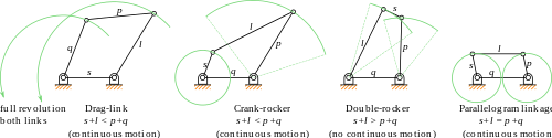
A mechanical linkage is an assembly of systems connected to manage forces and movement. The movement of a body, or link, is studied using geometry so the link is considered to be rigid. The connections between links are modeled as providing ideal movement, pure rotation or sliding for example, and are called joints. A linkage modeled as a network of rigid links and ideal joints is called a kinematic chain.

<span class="mw-page-title-main">Peaucellier–Lipkin linkage</span> Mechanical linkage capable of transforming rotary motion into linear motion

The Peaucellier–Lipkin linkage, invented in 1864, was the first true planar straight line mechanism – the first planar linkage capable of transforming rotary motion into perfect straight-line motion, and vice versa. It is named after Charles-Nicolas Peaucellier (1832–1913), a French army officer, and Yom Tov Lipman Lipkin (1846–1876), a Lithuanian Jew and son of the famed Rabbi Israel Salanter.

In physics, the degrees of freedom (DOF) of a mechanical system is the number of independent parameters that define its configuration or state. It is important in the analysis of systems of bodies in mechanical engineering, structural engineering, aerospace engineering, robotics, and other fields.

<span class="mw-page-title-main">Overconstrained mechanism</span> Moveable linkage with zero mobility

In mechanical engineering, an overconstrained mechanism is a linkage that has more degrees of freedom than is predicted by the mobility formula. The mobility formula evaluates the degree of freedom of a system of rigid bodies that results when constraints are imposed in the form of joints between the links.

Multibody system is the study of the dynamic behavior of interconnected rigid or flexible bodies, each of which may undergo large translational and rotational displacements.

In classical mechanics, a kinematic pair is a connection between two physical objects that imposes constraints on their relative movement (kinematics). German engineer Franz Reuleaux introduced the kinematic pair as a new approach to the study of machines that provided an advance over the motion of elements consisting of simple machines.

<span class="mw-page-title-main">Straight-line mechanism</span> Mechanisms generating real or approximate straight line motion

A straight-line mechanism is a mechanism that converts any type of rotary or angular motion to perfect or near-perfect straight-line motion, or vice versa. Straight-line motion is linear motion of definite length or "stroke", every forward stroke being followed by a return stroke, giving reciprocating motion. The first such mechanism, patented in 1784 by James Watt, produced approximate straight-line motion, referred to by Watt as parallel motion.

<span class="mw-page-title-main">Cognate linkage</span> Linkages of different dimensions with the same output motion

In kinematics, cognate linkages are linkages that ensure the same coupler curve geometry or input-output relationship, while being dimensionally dissimilar. In case of four-bar linkage coupler cognates, the Roberts–Chebyshev Theorem, after Samuel Roberts and Pafnuty Chebyshev, states that each coupler curve can be generated by three different four-bar linkages. These four-bar linkages can be constructed using similar triangles and parallelograms, and the Cayley diagram.

The Chebychev–Grübler–Kutzbach criterion determines the number of degrees of freedom of a kinematic chain, that is, a coupling of rigid bodies by means of mechanical constraints. These devices are also called linkages.

<span class="mw-page-title-main">Klann linkage</span> Planar mechanism designed to simulate the gait of legged animals

The Klannlinkage is a planar mechanism designed to simulate the gait of legged animal and function as a wheel replacement, a leg mechanism. The linkage consists of the frame, a crank, two grounded rockers, and two couplers all connected by pivot joints. It was developed by Joe Klann in 1994 as an expansion of Burmester curves which are used to develop four-bar double-rocker linkages such as harbor crane booms. It is categorized as a modified Stephenson type III kinematic chain.

<span class="mw-page-title-main">Mechanism (engineering)</span> Device used to transfer forces via non-electric means

In engineering, a mechanism is a device that transforms input forces and movement into a desired set of output forces and movement. Mechanisms generally consist of moving components which may include:

In kinematics, Burmester theory comprises geometric techniques for synthesis of linkages. It was introduced in the late 19th century by Ludwig Burmester (1840–1927). His approach was to compute the geometric constraints of the linkage directly from the inventor's desired movement for a floating link. From this point of view a four-bar linkage is a floating link that has two points constrained to lie on two circles.

<span class="mw-page-title-main">Dwell mechanism</span> Intermittent motion mechanism

A dwell mechanism is an intermittent motion mechanism that alternates forward and return motion with holding position(s).

<span class="mw-page-title-main">Leg mechanism</span> Mechanical system that walks

A leg mechanism is a mechanical system designed to provide a propulsive force by intermittent frictional contact with the ground. This is in contrast with wheels or continuous tracks which are intended to maintain continuous frictional contact with the ground. Mechanical legs are linkages that can have one or more actuators, and can perform simple planar or complex motion. Compared to a wheel, a leg mechanism is potentially better fitted to uneven terrain, as it can step over obstacles.

<span class="mw-page-title-main">Quick return mechanism</span> Mechanism to produce a reciprocating motion with different speeds in opposing directions

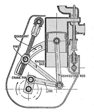
A quick return mechanism is an apparatus to produce a reciprocating motion in which the time taken for travel in return stroke is less than in the forward stroke. It is driven by a circular motion source and uses a system of links with three turning pairs and a sliding pair. A quick-return mechanism is a subclass of a slider-crank linkage, with an offset crank.

<span class="mw-page-title-main">Slider-crank linkage</span> Mechanism for conveting rotary motion into linear motion

A slider-crank linkage is a four-link mechanism with three revolute joints and one prismatic, or sliding, joint. The rotation of the crank drives the linear movement of the slider, or the expansion of gases against a sliding piston in a cylinder can drive the rotation of the crank.

In mechanical engineering, kinematic synthesis determines the size and configuration of mechanisms that shape the flow of power through a mechanical system, or machine, to achieve a desired performance. The word synthesis refers to combining parts to form a whole. Hartenberg and Denavit describe kinematic synthesis as

...it is design, the creation of something new. Kinematically, it is the conversion of a motion idea into hardware.

References

  1. Hartenberg, R.S. & J. Denavit (1964) Kinematic synthesis of linkages, New York: McGraw-Hill, online link from Cornell University.
  2. 1 2 3 4 J. M. McCarthy and G. S. Soh, Geometric Design of Linkages, 2nd Edition, Springer, 2010
  3. Cvetkovic, Ivana & Stojicevic, Misa & Popkonstantinović, Branislav & Cvetković, Dragan. (2018). Classification, geometrical and kinematic analysis of four-bar linkages. 261-266. 10.15308/Sinteza-2018-261-266.
  4. Design of Machinery 3/e, Robert L. Norton, 2 May 2003, McGraw Hill. ISBN   0-07-247046-1
  5. Toussaint, Godfried (2003). "Simple proofs of a geometric property of four-bar linkages" (PDF). American Mathematical Monthly. 110 (6): 482–494. doi:10.1080/00029890.2003.11919986. S2CID   16625019. Additional Proofs.
  6. 1 2 3 4 5 6 7 8 9 10 11 Myszka, David (2012). Machines and Mechanisms: Applied Kinematic Analysis. New Jersey: Pearson Education. ISBN   978-0-13-215780-3.
  7. Chakrabarti, Amaresh (2002). Engineering Design Synthesis: Understanding, Approaches and Tools. Great Britain: Springer-Verlag London Limited. ISBN   978-1852334925.
  8. Angeles, Jorge (2012), "The Dual Generalized Inverses and Their Applications in Kinematic Synthesis", Latest Advances in Robot Kinematics, Springer Netherlands, pp. 1–10, doi:10.1007/978-94-007-4620-6_1, ISBN   9789400746190
  9. Bennett, Geoffrey Thomas (1903). "A New Mechanism". Engineering . 76 (Dec 4, 1903): 777–778.
  10. Hunt, K. H., Kinematic Geometry of Mechanisms, Oxford Engineering Science Series, 1979
  11. Phoengsongkhro, S., Tangpornprasert, P., Yotnuengnit, P. et al. Development of four-bar polycentric knee joint with stance-phase knee flexion. Sci Rep 13, 22809 (2023). https://doi.org/10.1038/s41598-023-49879-4