Ackermann steering geometry

Last updated
Ackermann geometry Ackermann turning.svg
Ackermann geometry

The Ackermann steering geometry is a geometric arrangement of linkages in the steering of a car or other vehicle designed to solve the problem of wheels on the inside and outside of a turn needing to trace out circles of different radii.

Contents

It was invented by the German carriage builder Georg Lankensperger in Munich in 1816, then patented by his agent in England, Rudolph Ackermann (1764–1834) in 1818 for horse-drawn carriages. Erasmus Darwin may have a prior claim as the inventor dating from 1758. [1] He devised his steering system because he was injured when a carriage tipped over.

Advantages

The intention of Ackermann geometry is to avoid the need for tyres to slip sideways when following the path around a curve. [2] The geometrical solution to this is for all wheels to have their axles arranged as radii of circles with a common centre point. As the rear wheels are fixed, this centre point must be on a line extended from the rear axle. Intersecting the axes of the front wheels on this line as well requires that the inside front wheel be turned, when steering, through a greater angle than the outside wheel. [2]

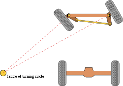
Rather than the preceding "turntable" steering, where both front wheels turned around a common pivot, each wheel gained its own pivot, close to its own hub. While more complex, this arrangement enhances controllability by avoiding large inputs from road surface variations being applied to the end of a long lever arm, as well as greatly reducing the fore-and-aft travel of the steered wheels. A linkage between these hubs pivots the two wheels together, and by careful arrangement of the linkage dimensions the Ackermann geometry could be approximated. This was achieved by making the linkage not a simple parallelogram, but by making the length of the track rod (the moving link between the hubs) shorter than that of the axle, so that the steering arms of the hubs appeared to "toe out". As the steering moved, the wheels turned according to Ackermann, with the inner wheel turning further. [2] If the track rod is placed ahead of the axle, it should instead be longer in comparison, thus preserving this same "toe out".

Design and choice of geometry

Ackermann simple design.svg
Simple approximation for designing Ackermann geometry
Ackerman Steering Linkage.gif
Ackermann steering linkage

A simple approximation to perfect Ackermann steering geometry may be generated by moving the steering pivot points[ clarification needed ] inward so as to lie on a line drawn between the steering kingpins, which is the pivot point, and the centre of the rear axle. [2] The steering pivot points[ clarification needed ] are joined by a rigid bar called the tie rod, which can also be part of the steering mechanism, in the form of a rack and pinion for instance. With perfect Ackermann, at any angle of steering, the centre point of all of the circles traced by all wheels will lie at a common point.

Modern cars do not use pure Ackermann steering, partly because it ignores important dynamic and compliant effects, but the principle is sound for low-speed maneuvers. Some racing cars use reverse Ackermann geometry to compensate for the large difference in slip angle between the inner and outer front tires while cornering at high speed. The use of such geometry helps reduce tyre temperatures during high-speed cornering but compromises performance in low-speed maneuvers. [3]

Extended Ackermann condition

Extended Ackermann condition ExtendedAckermann.gif
Extended Ackermann condition

The Ackermann condition of vehicle train is fulfilled when both the vehicle wheel and the trailer wheel axes are pointing to the theoretical turning center (momentan centrum). [4] Unlike single vehicles, having the steering wheels turned, the vehicle combinations have to travel a certain distance to have this condition formed.

See also

Related Research Articles

<span class="mw-page-title-main">Tricycle</span> Three-wheeled self-powered vehicle

A tricycle, sometimes abbreviated to trike, is a human-powered three-wheeled vehicle.

Vehicle dynamics is the study of vehicle motion, e.g., how a vehicle's forward movement changes in response to driver inputs, propulsion system outputs, ambient conditions, air/surface/water conditions, etc. Vehicle dynamics is a part of engineering primarily based on classical mechanics. It may be applied for motorized vehicles, bicycles and motorcycles, aircraft, and watercraft.

<span class="mw-page-title-main">Kingpin (automotive part)</span> Main pivot in a vehicles steering mechanism, or part of the fifth wheel coupling for a semi truck

The kingpin is the main pivot in the steering mechanism of a car or other vehicle.

<span class="mw-page-title-main">Steering</span> The control of the direction of motion of vehicles and other objects

Steering is the control of the direction of locomotion or the components that enable its control. Steering is achieved through various arrangements, among them ailerons for airplanes, rudders for boats, tilting rotors for helicopters, and many more.

<span class="mw-page-title-main">Multi-link suspension</span> A type of vehicle suspension

A multi-link suspension is a type of vehicle suspension with one or more transversal arms. A wider definition can consider any independent suspensions having three control links or more multi-link suspensions. These arms do not have to be of equal length, and may be angled away from their "obvious" direction. It was first introduced in the late 1960s on the Mercedes-Benz C111 and later on their W201 and W124 series.

<span class="mw-page-title-main">Car suspension</span> Suspension system for a vehicle

Suspension is the system of tires, tire air, springs, shock absorbers and linkages that connects a vehicle to its wheels and allows relative motion between the two. Suspension systems must support both road holding/handling and ride quality, which are at odds with each other. The tuning of suspensions involves finding the right compromise. It is important for the suspension to keep the road wheel in contact with the road surface as much as possible, because all the road or ground forces acting on the vehicle do so through the contact patches of the tires. The suspension also protects the vehicle itself and any cargo or luggage from damage and wear. The design of front and rear suspension of a car may be different.

<span class="mw-page-title-main">Double wishbone suspension</span> Automotive independent suspension design

A double wishbone suspension is an independent suspension design for automobiles using two wishbone-shaped arms to locate the wheel. Each wishbone or arm has two mounting points to the chassis and one joint at the knuckle. The shock absorber and coil spring mount to the wishbones to control vertical movement. Double wishbone designs allow the engineer to carefully control the motion of the wheel throughout suspension travel, controlling such parameters as camber angle, caster angle, toe pattern, roll center height, scrub radius, scuff, and more.

<span class="mw-page-title-main">Caster angle</span> The angle between the vertical axis and the steering axis of a steered wheel, in side view

The caster angle or castor angle is the angular displacement of the steering axis from the vertical axis of a steered wheel in a car, motorcycle, bicycle, other vehicle or a vessel, as seen from the side of the vehicle. The steering axis in a car with dual ball joint suspension is an imaginary line that runs through the center of the upper ball joint to the center of the lower ball joint, or through the center of the kingpin for vehicles having a kingpin.

<span class="mw-page-title-main">Toe (automotive)</span> Installing wheels on a vehicle so that the wheels faces are not completely parallel

In automotive engineering, toe, also known as tracking, is the symmetric angle that each wheel makes with the longitudinal axis of the vehicle, as a function of static geometry, and kinematic and compliant effects. This can be contrasted with steer, which is the antisymmetric angle, i.e. both wheels point to the left or right, in parallel (roughly). Negative toe, or toe out, is the front of the wheel pointing away from the centreline of the vehicle. Positive toe, or toe in, is the front of the wheel pointing towards the centreline of the vehicle. Historically, and still commonly in the United States, toe was specified as the linear difference of the distance between the two front-facing and rear-facing tire centerlines at the outer diameter and axle-height; since the toe angle in that case depends on the tire diameter, the linear dimension toe specification for a particular vehicle is for specified tires.

<span class="mw-page-title-main">Tilting three-wheeler</span> Tilting three-wheeled vehicle

A tilting three-wheeler, tilting trike, leaning trike, or even just tilter, is a three-wheeled vehicle and usually a narrow-track vehicle whose body and or wheels tilt in the direction of a turn. Such vehicles can corner without rolling over despite having a narrow axle track because they can balance some or all of the roll moment caused by centripetal acceleration with an opposite roll moment caused by gravity, as bicycles and motorcycles do. This also reduces the lateral acceleration experienced by the rider, which some find more comfortable than the alternative. The narrow profile can result in reduced aerodynamic drag and increased fuel efficiency. These types of vehicles have also been described as "man-wide vehicles" (MWV).

<span class="mw-page-title-main">Beam axle</span> Automobile mechanism

A beam axle, rigid axle or solid axle is a dependent suspension design in which a set of wheels is connected laterally by a single beam or shaft. Beam axles were once commonly used at the rear wheels of a vehicle, but historically they have also been used as front axles in four-wheel-drive vehicles. In most automobiles, beam axles have been replaced with front and rear independent suspensions.

DIRAVI is the name given by Citroën to its proprietary power steering system, first seen in 1970.

The following outline is provided as an overview of and topical guide to automobiles:

<span class="mw-page-title-main">Bump steer</span>

Bump steer is the term for the tendency of the wheel of a car to steer itself as it moves through the suspension stroke.

Automotive suspension design is an aspect of automotive engineering, concerned with designing the suspension for cars and trucks. Suspension design for other vehicles is similar, though the process may not be as well established.

<span class="mw-page-title-main">Arnoux system</span>

The Arnoux system is a train articulation system, for turning on railroad tracks, invented by Jean-Claude-Républicain Arnoux and patented in France in 1838. Arnoux was the chief engineer of the Ligne de Sceaux, which was originally built with very tight radii in the area around Sceaux, Hauts-de-Seine.

<span class="mw-page-title-main">Transverse leaf spring front suspension</span>

Transverse leaf spring front suspension is a type of automotive front suspension, whose usage is most well known in Ford Motor Company products from 1908 to 1948. "Suicide front axle" is a term that has been used for it.

<span class="mw-page-title-main">Clément-Panhard</span> Motor vehicle

Clément-Panhard is an automobile designed in 1898 by Arthur Constantin Krebs, manager of Panhard & Levassor co, from his 1896 patent of a car fitted with an electromagnetic gearbox, whose licence was acquired by Émile Levassor.

<span class="mw-page-title-main">Yamaha Niken</span> Three-wheeler motorcycle by Yamaha

The Yamaha Niken is a 845 cc tilting three-wheeler motorcycle, manufactured since 2018 by Yamaha Motor and sold worldwide.

References

  1. Erasmus Darwin's Improved Design for Steering Carriages by Desmond King-Hele , 2002, The Royal Society, London. Accessed April 2008.
  2. 1 2 3 4 Norris, William (1906). "Steering". Modern Steam Road Wagons. Longmans. pp. 63–67.
  3. Milliken, William F, and Milliken, Douglas L: "Race Car Vehicle Dynamics", Page 715. SAE 1995 ISBN   1-56091-526-9
  4. Szakács, Tamás (2010). "Modelling and simulation of tow angle between agricultural tractors and trailers". Landtechnik. 65 (3): 178–181. Retrieved 26 November 2020. In German: Szakács, Tamás (2010). "Modellierung und Simulation des Zugwinkels zwischen Anhänger und Zugmaschine". Landtechnik. 65 (3): 178–181. Retrieved 26 November 2020.