Vehicle dynamics is the study of vehicle motion, e.g., how a vehicle's forward movement changes in response to driver inputs, propulsion system outputs, ambient conditions, air/surface/water conditions, etc. Vehicle dynamics is a part of engineering primarily based on classical mechanics. It may be applied for motorized vehicles, bicycles and motorcycles, aircraft, and watercraft.

The Ackermann steering geometry is a geometric arrangement of linkages in the steering of a car or other vehicle designed to solve the problem of wheels on the inside and outside of a turn needing to trace out circles of different radii.

Camber angle is one of the angles made by the wheels of a vehicle; specifically, it is the angle between the vertical axis of a wheel and the vertical axis of the vehicle when viewed from the front or rear. It is used in the creation of steering and suspension. If the top of the wheel is farther out than the bottom, it is called positive camber; if the bottom of the wheel is farther out than the top, it is called negative camber.

Steering is the control of the direction of locomotion.

Suspension is the system of tires, tire air, springs, shock absorbers and linkages that connects a vehicle to its wheels and allows relative motion between the two. Suspension systems must support both road holding/handling and ride quality, which are at odds with each other. The tuning of suspensions involves finding the right compromise. It is important for the suspension to keep the road wheel in contact with the road surface as much as possible, because all the road or ground forces acting on the vehicle do so through the contact patches of the tires. The suspension also protects the vehicle itself and any cargo or luggage from damage and wear. The design of front and rear suspension of a car may be different.
Automobile handling and vehicle handling are descriptions of the way a wheeled vehicle responds and reacts to the inputs of a driver, as well as how it moves along a track or road. It is commonly judged by how a vehicle performs particularly during cornering, acceleration, and braking as well as on the vehicle's directional stability when moving in steady state condition.

A caster is an undriven wheel that is designed to be attached to the bottom of a larger object to enable that object to be moved.

In both road and rail vehicles, the wheelbase is the horizontal distance between the centers of the front and rear wheels. For road vehicles with more than two axles, the wheelbase is the distance between the steering (front) axle and the centerpoint of the driving axle group. In the case of a tri-axle truck, the wheelbase would be the distance between the steering axle and a point midway between the two rear axles.

A double wishbone suspension is an independent suspension design for automobiles using two wishbone-shaped arms to locate the wheel. Each wishbone or arm has two mounting points to the chassis and one joint at the knuckle. The shock absorber and coil spring mount to the wishbones to control vertical movement. Double wishbone designs allow the engineer to carefully control the motion of the wheel throughout suspension travel, controlling such parameters as camber angle, caster angle, toe pattern, roll center height, scrub radius, scuff, and more.

The caster angle or castor angle is the angular displacement of the steering axis from the vertical axis of a steered wheel in a car, motorcycle, bicycle, other vehicle or a vessel, as seen from the side of the vehicle. The steering axis in a car with dual ball joint suspension is an imaginary line that runs through the center of the upper ball joint to the center of the lower ball joint, or through the center of the kingpin for vehicles having a kingpin.
A swing axle is a simple type of independent suspension designed and patented by Edmund Rumpler in 1903. This was a revolutionary invention in automotive suspension, allowing driven (powered) wheels to follow uneven road surfaces independently, thus enabling the vehicle's wheels to maintain better road contact and holding; plus each wheel's reduced unsprung weight means their movements have less impact on the vehicle as a whole. The first automotive application was the Rumpler Tropfenwagen, later followed by the Mercedes 130H/150H/170H, the Standard Superior, the Volkswagen Beetle and its derivatives, the Chevrolet Corvair, and the roll-over prone M151 jeep amongst others.
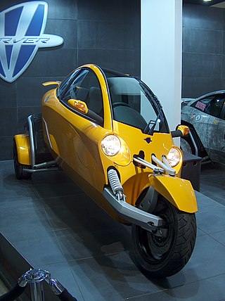
A tilting three-wheeler, tilting trike, leaning trike, or even just tilter, is a three-wheeled vehicle and usually a narrow-track vehicle whose body and or wheels tilt in the direction of a turn. Such vehicles can corner without rolling over despite having a narrow axle track because they can balance some or all of the roll moment caused by centripetal acceleration with an opposite roll moment caused by gravity, as bicycles and motorcycles do. This also reduces the lateral acceleration experienced by the rider, which some find more comfortable than the alternative. The narrow profile can result in reduced aerodynamic drag and increased fuel efficiency. These types of vehicles have also been described as "man-wide vehicles" (MWV).

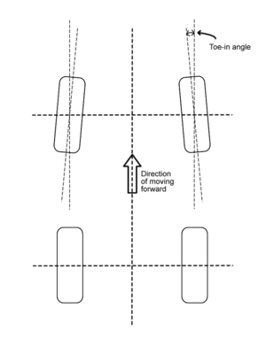
Wheel alignment, which is sometimes referred to as breaking or tracking, is part of standard automobile maintenance that consists of adjusting the angles of wheels to the car manufacturer specifications. The purpose of these adjustments is to reduce tire wear and to ensure that vehicle travel is straight and true. Alignment angles can also be altered beyond the maker's specifications to obtain a specific handling characteristic. Motorsport and off-road applications may call for angles to be adjusted well beyond normal, for a variety of reasons.

A beam axle, rigid axle or solid axle is a dependent suspension design in which a set of wheels is connected laterally by a single beam or shaft. Beam axles were once commonly used at the rear wheels of a vehicle, but historically they have also been used as front axles in four-wheel-drive vehicles. In most automobiles, beam axles have been replaced with front and rear independent suspensions.

Bicycle and motorcycle dynamics is the science of the motion of bicycles and motorcycles and their components, due to the forces acting on them. Dynamics falls under a branch of physics known as classical mechanics. Bike motions of interest include balancing, steering, braking, accelerating, suspension activation, and vibration. The study of these motions began in the late 19th century and continues today.
The following outline is provided as an overview of and topical guide to automobiles:
The scrub radius is the distance in front view between the king pin axis and the center of the contact patch of the wheel, where both would theoretically touch the road. It can be positive, negative or zero.
Bump steer is the term for the tendency of the wheel of a car to steer itself as it moves through the suspension stroke.

The twist-beam rear suspension is a type of automobile suspension based on a large H or C-shaped member. The front of the H attaches to the body via rubber bushings, and the rear of the H carries each stub-axle assembly, on each side of the car. The cross beam of the H holds the two trailing arms together, and provides the roll stiffness of the suspension, by twisting as the two trailing arms move vertically, relative to each other.

Camber thrust and camber force are terms used to describe the force generated perpendicular to the direction of travel of a rolling tire due to its camber angle and finite contact patch. Camber thrust is generated when a point on the outer surface of a leaned and rotating tire, that would normally follow a path that is elliptical when projected onto the ground, is forced to follow a straight path while coming in contact with the ground, due to friction. This deviation towards the direction of the lean causes a deformation in the tire tread and carcass that is transmitted to the vehicle as a force in the direction of the lean.