The Ackermann steering geometry is a geometric arrangement of linkages in the steering of a car or other vehicle designed to solve the problem of wheels on the inside and outside of a turn needing to trace out circles of different radii.

Camber angle is one of the angles made by the wheels of a vehicle; specifically, it is the angle between the vertical axis of a wheel and the vertical axis of the vehicle when viewed from the front or rear. It is used in the creation of steering and suspension. If the top of the wheel is farther out than the bottom, it is called positive camber; if the bottom of the wheel is farther out than the top, it is called negative camber.

The MacPherson strut is a type of automotive suspension system that uses the top of a telescopic damper as the upper steering pivot. It is widely used in the front suspension of modern vehicles. The name comes from American automotive engineer Earle S. MacPherson, who invented and developed the design.
Steering is the control of the direction of motion or the components that enable its control. Steering is achieved through various arrangements, among them ailerons for airplanes, rudders for boats, tilting rotors for helicopters, and many more.

Suspension is the system of tires, tire air, springs, shock absorbers and linkages that connects a vehicle to its wheels and allows relative motion between the two. Suspension systems must support both road holding/handling and ride quality, which are at odds with each other. The tuning of suspensions involves finding the right compromise. It is important for the suspension to keep the road wheel in contact with the road surface as much as possible, because all the road or ground forces acting on the vehicle do so through the contact patches of the tires. The suspension also protects the vehicle itself and any cargo or luggage from damage and wear. The design of front and rear suspension of a car may be different.
Understeer and oversteer are vehicle dynamics terms used to describe the sensitivity of the vehicle to changes in steering angle associated with changes in lateral acceleration. This sensitivity is defined for a level road for a given steady state operating condition by the Society of Automotive Engineers (SAE) in document J670 and by the International Organization for Standardization (ISO) in document 8855. Whether the vehicle is understeer or oversteer depends on the rate of change of the understeer angle. The Understeer Angle is the amount of additional steering that must be added in any given steady-state maneuver beyond the Ackermann steer angle. The Ackermann Steer Angle is the steer angle at which the vehicle would travel about a curve when there is no lateral acceleration required.

Independent suspension is any automobile suspension system that allows each wheel on the same axle to move vertically independently of the others. This is contrasted with a beam axle or deDion axle system in which the wheels are linked. "Independent" refers to the motion or path of movement of the wheels or suspension. It is common for the left and right sides of the suspension to be connected with anti-roll bars or other such mechanisms. The anti-roll bar ties the left and right suspension spring rates together but does not tie their motion together.
Automobile handling and vehicle handling are descriptions of the way a wheeled vehicle responds and reacts to the inputs of a driver, as well as how it moves along a track or road. It is commonly judged by how a vehicle performs particularly during cornering, acceleration, and braking as well as on the vehicle's directional stability when moving in steady state condition.

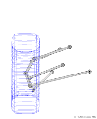
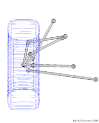
A double wishbone suspension is an independent suspension design for automobiles using two wishbone-shaped arms to locate the wheel. Each wishbone or arm has two mounting points to the chassis and one joint at the knuckle. The shock absorber and coil spring mount to the wishbones to control vertical movement. Double wishbone designs allow the engineer to carefully control the motion of the wheel throughout suspension travel, controlling such parameters as camber angle, caster angle, toe pattern, roll center height, scrub radius, scuff, and more.

A trailing-arm suspension, also referred to as trailing-link, is a form of vehicle suspension. In a motor vehicle it places one or more horizontal arms perpendicular to and forward of the axle on the chassis or unibody, which are connected to the axle or wheels with pivot joint(s). These are typically used on the rear axle or wheels of vehicles, but also found in both front and main landing gear of aircraft.

The Chapman strut is a design of independent rear suspension used for light cars, particularly sports and racing cars. It takes its name from, and is best known for its use by, Colin Chapman of Lotus.

An anti-roll bar is an automobile suspension part that helps reduce the body roll of a vehicle during fast cornering or over road irregularities. It links opposite front or rear wheels to a torsion spring using short lever arms for anchors. This increases the suspension's roll stiffness—its resistance to roll in turns.

In an automobile, ball joints are spherical bearings that connect the control arms to the steering knuckles, and are used on virtually every automobile made. They bionically resemble the ball-and-socket joints found in most tetrapod animals.

The Bowin P8 is a Formula 5000 and Formula 2 racing car, which was designed and built between 1972 and 1974 by Bowin.

Bicycle and motorcycle dynamics is the science of the motion of bicycles and motorcycles and their components, due to the forces acting on them. Dynamics falls under a branch of physics known as classical mechanics. Bike motions of interest include balancing, steering, braking, accelerating, suspension activation, and vibration. The study of these motions began in the late 19th century and continues today.
The Elfin MS8 Clubman is a sports car, successor to the Elfin MS7, a Repco-Holden V8 powered Group A Sports Car which won the 1975 Australian Sports Car Championship and the 1976 Australian Tourist Trophy.
Bump steer is the term for the tendency of the wheel of a car to steer itself as it moves through the suspension stroke.
Automotive suspension design is an aspect of automotive engineering, concerned with designing the suspension for cars and trucks. Suspension design for other vehicles is similar, though the process may not be as well established.

The twist-beam rear suspension is a type of automobile suspension based on a large H- or C-shaped member. The front of the H attaches to the body via rubber bushings, and the rear of the H carries each stub-axle assembly, on each side of the car. The cross beam of the H holds the two trailing arms together, and provides the roll stiffness of the suspension, by twisting as the two trailing arms move vertically, relative to each other.
The Audi R8 LMS Cup was a one-make sports car racing series by Audi based in Asia. Audi R8 LMS Cup cars were based on the Audi R8 LMS (GT3).