
A machine is a physical system that uses power to apply forces and control movement to perform an action. The term is commonly applied to artificial devices, such as those employing engines or motors, but also to natural biological macromolecules, such as molecular machines. Machines can be driven by animals and people, by natural forces such as wind and water, and by chemical, thermal, or electrical power, and include a system of mechanisms that shape the actuator input to achieve a specific application of output forces and movement. They can also include computers and sensors that monitor performance and plan movement, often called mechanical systems.
Steering is the control of the direction of motion or the components that enable its control. Steering is achieved through various arrangements, among them ailerons for airplanes, rudders for boats, cylic tilting of rotors for helicopters, and many more.
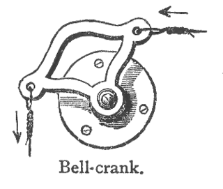
A bellcrank is a type of crank that changes motion through an angle. The angle can range from 0 to 360 degrees, but 90-degree and 180-degree bellcranks are most common.

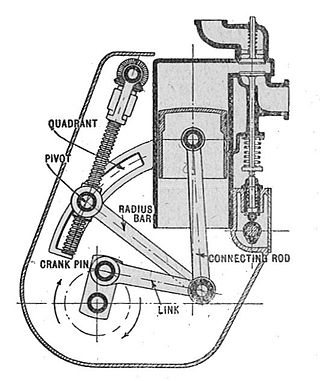
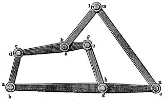
In kinematics, the parallel motion linkage is a six-bar mechanical linkage invented by the Scottish engineer James Watt in 1784 for the double-acting Watt steam engine. It allows a rod moving practically straight up and down to transmit motion to a beam moving in an arc, without putting significant sideways strain on the rod.
A Watt's linkage is a type of mechanical linkage invented by James Watt in which the central moving point of the linkage is constrained to travel a nearly straight path. Watt's described the linkage in his patent specification of 1784 for the Watt steam engine.
In the study of mechanisms, a four-bar linkage, also called a four-bar, is the simplest closed-chain movable linkage. It consists of four bodies, called bars or links, connected in a loop by four joints. Generally, the joints are configured so the links move in parallel planes, and the assembly is called a planar four-bar linkage. Spherical and spatial four-bar linkages also exist and are used in practice.
A mechanical linkage is an assembly of systems connected so as to manage forces and movement. The movement of a body, or link, is studied using geometry so the link is considered to be rigid. The connections between links are modeled as providing ideal movement, pure rotation or sliding for example, and are called joints. A linkage modeled as a network of rigid links and ideal joints is called a kinematic chain.
In physics, the degrees of freedom (DOF) of a mechanical system is the number of independent parameters that define its configuration or state. It is important in the analysis of systems of bodies in mechanical engineering, structural engineering, aerospace engineering, robotics, and other fields.

Reciprocating motion, also called reciprocation, is a repetitive up-and-down or back-and-forth linear motion. It is found in a wide range of mechanisms, including reciprocating engines and pumps. The two opposite motions that comprise a single reciprocation cycle are called strokes.
In mechanical engineering, an overconstrained mechanism is a linkage that has more degrees of freedom than is predicted by the mobility formula. The mobility formula evaluates the degree of freedom of a system of rigid bodies that results when constraints are imposed in the form of joints between the links.

In kinematics, the Chebyshev Lambda Linkage is a four-bar linkage that converts rotational motion to approximate straight-line motion with approximate constant velocity. It is so-named because it looks like a lowercase Greek letter lambda (λ). The precise design trades off straightness, lack of acceleration, and the proportion of the driving rotation that is spent in the linear portion of the full curve.

Bicycle suspension is the system, or systems, used to suspend the rider and bicycle in order to insulate them from the roughness of the terrain. Bicycle suspension is used primarily on mountain bikes, but is also common on hybrid bicycles.
In classical mechanics, a kinematic pair is a connection between two physical objects that imposes constraints on their relative movement (kinematics). German engineer Franz Reuleaux introduced the kinematic pair as a new approach to the study of machines that provided an advance over the notion of elements consisting of simple machines.
A straight-line mechanism is a mechanism that converts any type of rotary or angular motion to perfect or near-perfect straight-line motion, or vice versa. Straight-line motion is linear motion of definite length or "stroke", every forward stroke being followed by a return stroke, giving reciprocating motion. The first such mechanism, patented in 1784 by James Watt, produced approximate straight-line motion, referred to by Watt as parallel motion.

In kinematics, Chebyshev's linkage is a four-bar linkage that converts rotational motion to approximate linear motion.

In kinematics, cognate linkages are linkages that ensure the same coupler curve geometry or input-output relationship, while being dimensionally dissimilar. In case of four-bar linkage coupler cognates, the Roberts–Chebyshev Theorem, after Samuel Roberts and Pafnuty Chebyshev, states that each coupler curve can be generated by three different four-bar linkages. These four-bar linkages can be constructed using similar triangles and parallelograms, and the Cayley diagram.

In engineering, a mechanism is a device that transforms input forces and movement into a desired set of output forces and movement. Mechanisms generally consist of moving components which may include Gears and gear trains; Belts and chain drives; cams and followers; Linkages; Friction devices, such as brakes or clutches; Structural components such as a frame, fasteners, bearings, springs, or lubricants; Various machine elements, such as splines, pins, or keys.
In mechanics, a six-bar linkage is a mechanism with one degree of freedom that is constructed from six links and seven joints. An example is the Klann linkage used to drive the legs of a walking machine.
A dwell mechanism is an intermittent motion mechanism that alternates forward and return motion with holding position(s).
A slider-crank linkage is a four-link mechanism with three revolute joints and one prismatic (sliding) joint. The rotation of the crank drives the linear movement of the slider, or the expansion of gases against a sliding piston in a cylinder can drive the rotation of the crank.


