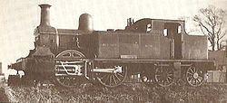
A set of Walschaerts valve gear on 60163 Tornado. Note that the radius bar is set to reverse.
The Walschaerts valve gear, known as Heusinger valve gear in parts of Europe, is a type of valve gear used to regulate the flow of steam to the pistons in steam locomotives, invented by Belgian railway engineerEgide Walschaerts in 1844.[1][2] The gear is sometimes named without the final "s",[a] since it was incorrectly patented under that name. It was extensively used in steam locomotives from the late 19th century until the end of the steam era.
The Walschaerts valve gear was slow to gain popularity. The Stephenson valve gear remained the most commonly used valve gear on 19th-century locomotives. However, the Walschaerts valve gear had the advantage that it could be mounted entirely on the outside of the locomotives, leaving the space between the frames clear and allowing easy access for service and adjustment, which resulted in it being adopted in some articulated locomotives.
The first locomotive fitted with the Walschaerts valve gear was built in 1849 at the Belgian Tubize workshops.
Egide Walschaerts was awarded a gold medal, honorable mentions and a diploma at the 1878 Universal Exhibition in Paris, and also in Antwerp in 1883.
In 1874, New Zealand Railways ordered two NZR B class locomotives. They were Double Fairlie locomotives, supplied by Avonside; the first use in New Zealand of Walschaerts valve gear and probably the first time that a British manufacturer had supplied it. They were Cape gauge.
The Mason Bogie, a modified Fairlie locomotive of 1874, was the first to use the Walschaerts gear in North America.
The first application in Britain was on a Single Fairlie 0-4-4T, exhibited in Paris in 1878 and purchased by the Swindon, Marlborough and Andover Railway in March 1882.[3] According to Ernest Ahrons,[4] the locomotive saw very little service as nobody seems to have known how to set the valves and this led to enormous coal consumption.
In the 20th century, the Walschaerts valve gear[5] was the most commonly used type, especially on larger locomotives. In Europe, its use was almost universal, whilst in North America, the Walschaerts gear outnumbered its closest competitor, the derived Baker valve gear, by a wide margin.
In Germany and some neighbouring countries, like Poland and Czechoslovakia, the Walschaerts gear is generally named the Heusinger valve gear after Edmund Heusinger von Waldegg, who invented the mechanism independently in 1849. Heusinger's gear was closer to the form generally adopted, but most authorities accept Walschaerts' invention as sufficiently close to the final form.
Purpose
The Walschaerts valve gear is an improvement on the earlier Stephenson valve gear in that it enables the driver to operate the steam engine in a continuous range of settings from maximum economy to maximum power. At any setting, the valve gear satisfies the following two conditions:
The valve opens to admit steam to the cylinder just before the start of a piston stroke. The pressure of this steam provides the driving force.
Soon before the space on one side of the piston starts to contract, the valve starts to release steam from that space to the atmosphere, so as not to impede the movement of the piston.
In an economical setting, steam is admitted to the expanding space for only part of the stroke; at a point set by the driver, the intake is cut off. Since the exhaust is also shut, during the rest of the stroke the steam that has entered the cylinder expands in isolation, and so its pressure decreases. Thus, the most energy available from the steam (in the absence of a condenser) is used.
The Walschaerts valve gear enables the engine driver to change the cutoff point without changing the points at which intake starts.
Economy also requires that the throttle be wide open and that the boiler pressure is at the maximum safe level to maximise thermal efficiency. For economy, a steam engine is used of a size such that the most economical settings yield the right amount of power most of the time, such as when a train is running at steady speed on level track.
When greater power is necessary, e.g. when gaining speed when pulling out of a station and when ascending a gradient, the Walschaerts valve gear enables the engine driver to set the cutoff point near the end of the stroke, so that the full pressure of the boiler is exerted on the piston for almost the entire stroke. With such a setting, when the exhaust opens, the steam in the cylinder is near full boiler pressure. The pressure in the steam at that moment serves no useful purpose; it drives a sudden pulse of pressure into the atmosphere and is wasted .
This sudden pulse of pressure causes the loud puffing sound that members of the public associate with steam engines, because they mostly encounter engines at stations, where efficiency is sacrificed as trains pull away. A steam engine well adjusted for efficiency makes a soft hissing sound that lasts throughout the exhaust stroke, with the sounds from the two cylinders overlapping to produce a nearly constant sound.
Motion
Walschaerts In movement
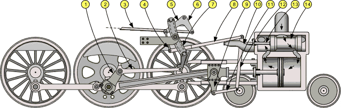
The valve gear operation combines two motions; one is the primary lead motion which is imparted at the bottom of the combination lever (12). The secondary is the directional/amplitude motion which is imparted at the top. Consider that the driver has adjusted the reversing lever such that the die block is at mid-gear. In this position the secondary motion is eliminated and the piston valve travel is shortest, giving minimal injection and exhaust of steam. The travel of the piston valve is twice the total of lap plus lead.
Contrast this to when the die block is at the bottom of the expansion link (7), giving maximum steam injection and exhaust. This is the most powerful forward setting and is used in accelerating forward from rest. Conversely when the die block is at the top of the expansion link (7), maximal power in reverse is obtained. (On some engines the die block was in the top of the link in forward gear. This type was generally used on tank engines, which worked in forward and reverse equally.[6])
Once the locomotive has accelerated the driver can adjust the reverser toward the mid-gear position, decreasing cut-off to give a more economical use of steam. The engine's tractive effort is then less than it was at starting, but its power is greater.
Technical details
The key components of Walschaerts Valve Gear:
Eccentric crank (UK: return crank)
Eccentric rod
Reach rod
Lifting link
Lifting arm
Reverse arm
Expansion link
Radius bar
Crosshead arm (UK Drop link)
Valve stem guide
Union link
Combination lever
Valve stem
Piston valve
The primary lead motion is provided by the crosshead arm (9) and the union link (11). This pivoting bar gives the in phase component of motion to the bottom of the combination lever (12).
The secondary directional/amplitude motion is derived from a mechanical linkage made up of several components.
The eccentric crank (UK: return crank) (1) is rigidly attached to the con-rod pin connected to the main drive wheel. Note that this is the only suitable attachment point on any of the drive wheels that is not fouled by the passage of the coupling rod or the connecting rod. The eccentric crank is of a length such that the pin attachment to the eccentric rod (2) is 90 degrees out of phase with the lead motion.
The eccentric rod provides motion to the expansion link (7) which is pivoted in a central location back to the body of the locomotive. The expansion link holds the radius bar (8), captive by a die block which is integral with the radius bar but is free to move vertically in a constrained curved path along the expansion link.
The vertical position of the radius bar is controlled in the cab by the driver adjusting the reverser which in turn controls the mechanical linkage; reach rod (3), lifting link (4), lifting arm (5) and reverse arm and shaft (6).
In this way the secondary, out of phase, driver controlled component of motion is imparted to the top of the combination lever (12) by the radius bar (8).
The combination lever combines these two motions with the resultant acting upon the valve stem (13), suitably restrained by the valve stem guide (10), which in turn acts upon the piston valve (14).
Inside and outside admission valves
The Walschaerts gear can be linked to inside or outside admission valves. This article has only considered inside-admission piston valves until now, but outside-admission valves (slide valves and some piston valves) can use Walschaerts valve gear. If the valves have outside admission the radius bar connects to the combination lever below the valve stem rather than above and the orientation of the eccentric crank is changed so that it leads, rather than trails, the main crank pin.
To lay out Walschaerts gear, the proportions of the combination lever must be chosen. A displacement of the union link end by half the piston travel must cause a valve rod displacement of the valve lead plus the valve lap. The ratio of distance from union link end to pivot with radius rod to the distance between the valve rod end to the pivot with the radius rod should be in the same proportion as half piston travel to valve lap plus lead.
When the piston is at either dead centre movement of the radius rod should not move the valve rod. Therefore the expansion link die slot should be an arc of a circle of radius equal to the length of the radius rod.
The throw of the return crank must give the required oscillation of the expansion link.
Variants
There have been many variants of Walschaerts valve gear, including:
↑Sands, T.B. & Jenkins, Stanley C. (1990) [1959]. The Midland and South Western Junction Railway. The Oakwood Library of Railway History (2nded.). Headington: Oakwood Press. pp.37, 43. ISBN0-85361-402-4. OL16.
↑Ahrons, E. L. (1953). Locomotive and Train working in the latter part of the 19th Century. Vol.4. Cambridge: Heffer. p.122.
See The Encyclopedia of Railroads, O. S. Nock, 1977 The name is Walschaert, changed by the family in 1830 when Belgium became independent of the Netherlands. It was patented under the name Walschaert because that is how the name was spelled in 1844.
This page is based on this Wikipedia article Text is available under the CC BY-SA 4.0 license; additional terms may apply. Images, videos and audio are available under their respective licenses.