Piston valve (steam engine)

Last updated
Diagram of cylinder and piston valve. The valve is next opened by moving it to the right, allowing the clear space in the middle of the valve to align with the channel in the cylinder above it. Cylinder and piston valve (New Catechism of the Steam Engine, 1904).jpg
Diagram of cylinder and piston valve. The valve is next opened by moving it to the right, allowing the clear space in the middle of the valve to align with the channel in the cylinder above it.

Piston valves are one form of valve used to control the flow of steam within a steam engine or locomotive. They control the admission of steam into the cylinders and its subsequent exhausting, enabling a locomotive to move under its own power. The valve consists of two piston heads on a common spindle moving inside a steam chest, which is essentially a mini-cylinder located either above or below the main cylinders of the locomotive.

Contents

Overview

In the 19th century, steam locomotives used slide valves to control the flow of steam into and out of the cylinders. In the 20th century, slide valves were gradually superseded by piston valves, particularly in engines using superheated steam. There were two reasons for this:

The usual locomotive valve gears such as Stephenson, Walschaerts, and Baker valve gear, can be used with either slide valves or piston valves. Where poppet valves are used, a different gear, such as Caprotti valve gear may be used, though standard gears as mentioned above were used as well, by Chapelon and others.

Most piston valves are of the "inside admission" type, where fresh steam is introduced from the boiler via the space between the two piston heads of the valve, and exhaust steam leaves via the space between a piston head and the end of the steam chest. The advantage of this arrangement is that leakage, via the gland which seals the steam chest from the operating rod of the valve gear, is much less of a problem when the gland is subjected to low exhaust pressure rather than full boiler pressure. However, some locomotives, like Bulleid's SR Merchant Navy class, used "outside admission" where the reverse was true, in Bulleid's case because of the unusual chain-driven valve gear arrangement.

Examples

The Swannington incline winding engine of 1833 incorporated a piston valve SwanningtonEngine 01.jpg
The Swannington incline winding engine of 1833 incorporated a piston valve

The Swannington incline winding engine on the Leicester and Swannington Railway, manufactured by The Horsely Coal & Iron Company in 1833, shows a very early use of the piston valve. [1] Piston valves had been used a year or two previously in the horizontal engines manufactured by Taylor & Martineau of London, but did not become general for stationary or locomotive engines until the end of the 19th century. [2]

Design principles

Diagram showing lap and lead and their relation to valve travel Steam engine Lap and lead diagram.png
Diagram showing lap and lead and their relation to valve travel

When on the move, a steam locomotive requires steam to enter the cylinder at precise times relative to the piston's position. [3] This entails controlling the admission and exhaust of steam to and from the cylinders with a valve linked to the motion of the piston. [3]

For timing and dimensioning of slide or piston valves where the valve opens and closes the steam and exhaust ports, a consideration of the "lap" and "lead" is required.

Lap

Lap is the amount by which the valve overlaps each port at the middle position of each valve. [3] There are two different types of lap.

The first kind is the steam lap, which is the amount by which the valve overlaps the steam port on the live steam side of the piston or slide valve (i.e. the distance the valve needs to move to just begin to uncover the port). [3]

Secondly, the exhaust lap, which is the amount by which the valve overlaps the exhaust port on the exhaust side of the piston or slide valve. Exhaust lap is generally given to slow-running locomotives. [3] This is because it allows the steam to remain in the cylinder for the longest possible amount of time before being expended as exhaust, therefore increasing efficiency. [3] shunter locomotives tended to be equipped with this addition.

Negative exhaust lap, also commonly known as exhaust clearance, is the amount the port is open to exhaust when the valve is in mid-position, and is used on many fast-running locomotives to give a free exhaust. [3] The cylinder on both sides of the piston is open to exhaust at the same time when the valve is passing through the mid-position, which is only momentary when running. [3]

Lead

Lead is the amount by which a port is open when the piston is at front or back "dead centre". [3] In the case of the steam port this allows admission of steam to fill the clearance space between the cylinder and piston and ensures maximum cylinder pressure before the commencement of the stroke. [3] This both cushions and assists the mass of the piston to slow down and change direction. At slow speeds no lead is ideal. For engines with pistons of 24 inches plus and masses of over 5 kilos and pressures under 500 psi then cushioning is beneficial. Lead is necessary on locomotives designed for high speeds. [3]

Calculating valve events

Given the valve's lap, lead, and travel, at what point in the piston's stroke does the valve open and close, to steam and to exhaust?

Calculating an exact answer to that question before computers was too much work. The easy approximation (used in Zeuner's and Realeaux's diagrams) is to pretend that both the valve and the piston have a sine-wave motion (as they would, if the main rod were infinitely long). Then, for instance, to calculate the percent of the piston's stroke at which steam admission is cut off:

Add the two angles and take the cosine of their sum; subtract 1 from that cosine and multiply the result by -50.

As built the Pennsylvania's I1s 2-10-0 had lap 2 inches, lead 1/4 inch and valve travel 6 inches in full gear. In full gear the two angles are 48.19 deg and 41.41 deg and the maximum cutoff comes out 49.65% of the piston stroke.

See also

Related Research Articles

Steam engine Heat engine that performs mechanical work using steam as its working fluid

A steam engine is a heat engine that performs mechanical work using steam as its working fluid. The steam engine uses the force produced by steam pressure to push a piston back and forth inside a cylinder. This pushing force can be transformed, by a connecting rod and crank, into rotational force for work. The term "steam engine" is generally applied only to reciprocating engines as just described, not to the steam turbine. Steam engines are external combustion engines, where the working fluid is separated from the combustion products. The ideal thermodynamic cycle used to analyze this process is called the Rankine cycle. In general usage, the term steam engine can refer to either complete steam plants, such as railway steam locomotives and portable engines, or may refer to the piston or turbine machinery alone, as in the beam engine and stationary steam engine.

Poppet valve Type of valve

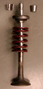
A poppet valve is a valve typically used to control the timing and quantity of gas or vapor flow into an engine.

Valve gear Mechanism for controlling steam flow in a reciprocating steam engine.

The valve gear of a steam engine is the mechanism that operates the inlet and exhaust valves to admit steam into the cylinder and allow exhaust steam to escape, respectively, at the correct points in the cycle. It can also serve as a reversing gear. It is sometimes referred to as the "motion".

Compound steam engine Steam engine where steam is expanded in stages

A compound steam engine unit is a type of steam engine where steam is expanded in two or more stages. A typical arrangement for a compound engine is that the steam is first expanded in a high-pressure (HP) cylinder, then having given up heat and losing pressure, it exhausts directly into one or more larger-volume low-pressure (LP) cylinders. Multiple-expansion engines employ additional cylinders, of progressively lower pressure, to extract further energy from the steam.

Walschaerts valve gear Type of valve gear

The Walschaerts valve gear is a type of valve gear invented by Belgian railway mechanical engineer Egide Walschaerts in 1844 used to regulate the flow of steam to the pistons in steam locomotives. The gear is sometimes named without the final "s", since it was incorrectly patented under that name. It was extensively used in steam locomotives from the late 19th century until the end of the steam era.

In a piston engine, the valve timing is the precise timing of the opening and closing of the valves. In an internal combustion engine those are usually poppet valves and in a steam engine they are usually slide valves or piston valves.

Slide valve

The slide valve is a rectilinear valve used to control the admission of steam into and emission of exhaust from the cylinder of a steam engine.

Corliss steam engine Type of steam engine using rotary steam valves

A Corliss steam engine is a steam engine, fitted with rotary valves and with variable valve timing patented in 1849, invented by and named after the American engineer George Henry Corliss of Providence, Rhode Island.

Uniflow steam engine

The uniflow type of steam engine uses steam that flows in one direction only in each half of the cylinder. Thermal efficiency is increased by having a temperature gradient along the cylinder. Steam always enters at the hot ends of the cylinder and exhausts through ports at the cooler centre. By this means, the relative heating and cooling of the cylinder walls is reduced.

Bulleid chain-driven valve gear

The Bulleid chain-driven valve gear is a type of steam locomotive valve gear designed by Oliver Bulleid during the Second World War for use on his Pacific (4-6-2) designs. It was peculiar to the Southern Railway in Britain, and borrowed from motor-vehicle practice in an attempt to create a compact and efficient design with a minimum of service requirements.

A compound locomotive is a steam locomotive which is powered by a compound engine, a type of steam engine where steam is expanded in two or more stages. The locomotive was only one application of compounding. Two and three stages were used in ships, for example.

Expansion valve (steam engine)

An expansion valve is a device in steam engine valve gear that improves engine efficiency. It operates by closing off the supply of steam early, before the piston has travelled through its full stroke. This cut-off allows the steam to then expand within the cylinder. This expanding steam is still sufficient to drive the piston, even though its pressure decreases as it expands. As less steam is supplied in the shorter time for which the valve is open, use of the expansion valve reduces the steam consumed and thus the fuel required. The engine may deliver two-thirds of the work, for only one-third of the steam.

A Johnson Bar is a control lever on a steam locomotive, used to control the timing of the admission of steam into the locomotive's cylinders. By controlling this timing, the amount of power delivered to the wheels is regulated, as is the direction that the wheels rotate, giving the lever the alternate name of the reversing lever. This is the term employed in British English, while the term 'Johnson Bar' is the norm in the United States.

South African Class 10B 4-6-2

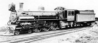
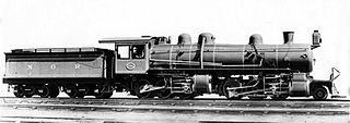
The South African Railways Class 10B 4-6-2 of 1910 was a steam locomotive from the pre-Union era in Transvaal.

South African Class 10A 4-6-2

The South African Railways Class 10A 4-6-2 of 1910 was a steam locomotive from the pre-Union era in Transvaal.

South African Class Experimental 2 2-8-0

The South African Railways Class Experimental 2 2-8-0 of 1902 was a steam locomotive from the pre-Union era in the Cape of Good Hope.

South African Class MA 2-6-6-0

The South African Railways Class MA 2-6-6-0 of 1909 was a steam locomotive from the pre-Union era in the Natal Colony.

South African Class MD 2-6-6-2

The South African Railways Class MD 2-6-6-2 of 1910 was a steam locomotive from the pre-Union era in Transvaal.

Trofimoff valve

The Trofimoff valve is a springless pressure-compensation piston valve for steam locomotives.

Willans engine

The Willans engine or central valve engine was a high-speed stationary steam engine used mainly for electricity generation around the start of the 20th century.

References

  1. Clinker, C.R. (1977) The Leicester & Swannington Railway Bristol: Avon Anglia Publications & Services. Reprinted from the Transactions of the Leicestershire Archaeological Society Volume XXX, 1954.
  2. Information plaque on the Swannington engine, National Railway Museum, York.
  3. 1 2 3 4 5 6 7 8 9 10 11 Garratt, C. & Wade-Matthews, M.: The Ultimate Encyclopedia of Steam & Rail (London: Hermes Publishing Company, Ltd., 1998) ISBN   1-84038-088-8