British LMS Stanier Class 5 4-6-0 Locomotive no. 44767 showing experimental Stephenson valve gear unusually mounted outside the framesA simple Stephenson gear in partial cutoff
The Stephenson valve gear or Stephenson link or shifting link[1] is a simple design of valve gear that was widely used throughout the world for various kinds of steam engines. It is named after Robert Stephenson[2] but was invented by his employees.
During the 1830s, the most popular valve drive for steam locomotives was known as gab motion in the United Kingdom and V-hook motion in the United States.[3] The gab motion incorporated two sets of eccentrics and rods for each cylinder; one eccentric was set to give forward and the other backwards motion to the engine and one or the other could accordingly engage with a pin driving the distribution valve by means of the gabs: - vee-shaped ends to the eccentric rods supposed to catch the rocker driving the valve rod whatever its position. It was a clumsy mechanism, difficult to operate, and only gave fixed valve events.
Inside Stephenson valve gear as applied to a French 0-6-0 outside cylinder mixed traffic locomotive (Midi 801) in 1867
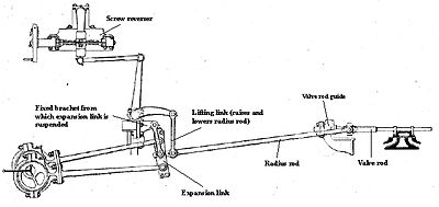
In 1841, two employees of Robert Stephenson and Company, draughtsman William Howe and pattern-maker William Williams, suggested the simple expedient of replacing the gabs with a vertical slotted link, pivoted at both ends to the tips of the eccentric rods. To change direction, the link and rod ends were bodily raised or lowered by means of a counterbalanced bell crank worked by a reach rod that connected it to the reversing lever. This not only simplified reversing but it was realised that the gear could be raised or lowered in small increments, and thus the combined motion from the “forward” and “back” eccentrics in differing proportions would impart shorter travel to the valve, cutting off admission steam earlier in the stroke and using a smaller amount steam expansively in the cylinder, using its own energy rather than continuing to draw from the boiler. It became the practice to start the engine or climb gradients at long cutoff, usually about 70-80% maximum of the power stroke and to shorten the cutoff as momentum was gained to benefit from the economy of expansive working and the effect of increased lead and higher compression at the end of each stroke. This process was popularly known as "linking up" or “notching up”, the latter because the reversing lever could be held in precise positions by means of a catch on the lever engaging notches in a quadrant; the term stuck even after the introduction of the screw reverser.
A further intrinsic advantage of the Stephenson gear not found in most other types was variable lead. Depending on how the gear was laid out, it was possible to considerably reduce compression and back pressure at the end of each piston stroke when working at low speed in full gear; once again as momentum was gained and cutoff shortened, so lead was automatically advanced and compression increased, cushioning the piston at the end of each stroke and heating the remaining trapped steam in order to avoid temperature drop in the fresh charge of incoming admission steam.
American locomotives universally employed inside Stephenson valve gear placed between the frames until around 1900 when it quickly gave way to outside Walschaerts motion. In Europe, Stephenson gear could be placed either outside the driving wheels and driven by either eccentrics or return cranks or else between the frames driven from the axle through eccentrics, as was mostly the case in Great Britain.
Applications
Abner Doble[4] considered Stephenson valve gear: "(...) the most universally suitable valve gear of all, for it can be worked out for a long engine structure or a short one. It can be a very simple valve gear and still be very accurate, but its great advantage is that its accuracy is self-contained, for the exact relationship between its points of support (eccentrics on shaft, valve crosshead, and link hanger arm) have but little effect on the motion of the valve. Its use on engines in which all the cylinders lie in one plane, represents, in the belief of the writer, the best choice." Another benefit of the Stephenson gear, intrinsic to the system, is variable lead: usually zero in full gear and increasing as cutoff is shortened. One consequent disadvantage of the Stephenson gear is that it has a tendency to over-compression at the end of the stroke when very short cut-offs are used, and therefore the minimum cut-off cannot be as low as on a locomotive with Walschaerts gear. Longer eccentric rods and a shorter link reduce this effect.
Stephenson valve gear is a convenient arrangement for any engine that needs to reverse and was widely applied to railway locomotives, traction engines, steam car engines and to stationary engines that needed to reverse, such as rolling-mill engines. It was used on the overwhelming majority of marine engines. The Great Western Railway used Stephenson gear on most of its locomotives, although the later four-cylinder engines used inside Walschaerts gear.
Details of the gear differ principally in the arrangement of the expansion link. In early locomotive practice, the eccentric rod ends were pivoted at the ends of the link while, in marine engines, the eccentric rod pivots were set behind the link slot (or below on a vertical engine). These became known respectively as the 'locomotive link' and the 'launch link'. The launch link superseded the locomotive type as it allows more direct linear drive to the piston rod in full gear and permits a longer valve travel within a given space by reducing the size of eccentric required for a given travel. Launch-type links were pretty well universal for American locomotives right from the 1850s but, in Europe, although occurring as early as 1846, they did not become widespread until around 1900. Larger marine engines generally used the bulkier and more expensive marine double-bar link, which has greater wearing surfaces and which improved valve events by minimising geometric compromises inherent in the launch link.
In the United Kingdom, locomotives having Stephenson valve gear normally had this mounted in between the locomotive frames. In 1947, the London, Midland and Scottish Railway built a series of their Stanier Class 5 4-6-0 locomotives, most of which had the Walschaerts' valve gear that was normal for this class, but one of them, no. 4767, had Stephenson valve gear mounted outside the wheels and frames. Instead of eccentrics, double return cranks were used to drive the eccentric rods, and a launch-type expansion link was used. This one cost £13,278, which was about £600 more than those built at the same time with Walschaerts' valve gear. The aim of the experiment was to find out if a valve gear having variable lead (as opposed to the constant lead of the Walschaerts' motion) would affect performance. On trial, it proved to have no advantage, although in normal service it did gain a reputation as a good performer on banks.[5][6][7][8][9]
Derivatives
As a harmonic valve gear, the Stephenson arrangement may be considered as optimum. Nevertheless, the fact the link needed to be bodily displaced in order to reverse meant that it required considerable vertical clearance. At the time of its introduction, it was deemed important in the locomotive world to keep the centre of gravity, and therefore the boiler centre line as low as possible. Because valve gears in Britain were generally placed between the frames beneath the boiler, the extremely cramped conditions made the valve gear inaccessible for servicing. Also reversing could be a strenuous occupation as it entailed lifting the weight of the link plus eccentric rod ends. In order to address these problems two main variants were developed:
Gooch valve gear
Gooch outside valve gear as applied to a French 2-4-0 outside cylinder express locomotive (Midi no. 51) in 1878
In the Gooch valve gear (invented by Daniel Gooch in 1843) the reversing and cut-off functions were achieved by raising or lowering a radius rod which connected the valve-rod to a "stationary" link pivoting around a fixed point. The advantages sought were reduced height for the gear and lighter action as the reversing lever was only required to lift the weight of the radius rod. This meant that the link was convex (in relation to the eccentrics) instead of concave. Gooch valve gear had the disadvantage of angularity between the valve spindle and the eccentric rod in full gear, whereas the best forms of the Stephenson gear, the thrust was in a straight line. The Gooch gear gave constant lead at whatever cutoff. This was observed to be a disadvantage when similar locomotives fitted with either Gooch or Stephenson gear were compared in service[10] Gooch gear was never popular in Britain except with one or two engineers down to the 1860s, but it was quite common in France.
Allan straight link valve gear
The Allan straight link valve gear (invented by Alexander Allan in 1855) combined the features of the Stephenson and Gooch gears. The reversing and cut-off functions were achieved by simultaneously raising the radius rod and lowering the link or vice versa. As with the Gooch gear, this saved space but the Allan gear gave performance closer to that of the Stephenson. Moreover, the straight expansion link simplified manufacture. Once again, the Allan gear was not often used in the UK but fairly common on the Continent. Notable UK examples are the Great Western Railway's 1361 and 1366 classes, and the narrow-gauge Ffestiniog Railway's 0-4-0TT class (which were produced by George England and Co.). Talyllyn Railway's second locomotive, Dolgoch (which was produced by Fletcher, Jennings & Co.) is provided with Fletcher's patent arrangement of Allan straight link gear.
See also
Walschaerts valve gear invented by Belgian railway mechanical engineer Egide Walschaerts in 1844 becoming the most widely used valve gear in Europe and North America.
Baker valve gear invented by American engineers in 1903 and widely used in North America.
Caprotti valve gear invented in the early 1920s by Italian architect and engineer Arturo Caprotti based on automotive valves it uses camshafts and poppet valves. Considered more efficient than any other method.
References
↑ Snell, J B (1971). Mechanical Engineering: Railways, Longman & Co, London
↑ White, John H. Jr. (1968): A History of the American locomotive, its development: 1830-1880; Dover republication of 1979, ISBN0-486-23818-0, original published by the Johns Hopkins Press.
↑ Walton J.N. (1965–74) Doble Steam Cars, Buses, Lorries, and Railcars . "Light Steam Power" Isle of Man, UK; p. 196.
↑ Rowledge, John Westbury Peter; Reed, Brian (1984) [1977]. The Stanier 4-6-0s of the LMS. Newton Abbot: David & Charles. pp.62–63. ISBN0-7153-7385-4.
↑ Nock, O.S. (1989). Great Locomotives of the LMS. Wellingborough: Patrick Stephens Ltd. pp.256–7. ISBN1-85260-020-9.
↑ Hunt, David; James, Fred; Essery, R.J.; Jennison, John; Clarke, David (2004). LMS Locomotive Profiles, no. 6 – The Mixed Traffic Class 5s – Nos. 5225–5499 and 4658–4999. Didcot: Wild Swan. pp.39–43, 85. ISBN1-874103-93-3.
↑ Jennison, John; Clarke, David; Hunt, David; James, Fred; Essery, R.J. (2004). Pictorial Supplement to LMS Locomotive Profile no. 6 – The Mixed Traffic Class 5s – part 2, nos. 5225–5499 and 4658–4999. Didcot: Wild Swan. pp.28–29, 31. ISBN1-874103-98-4.
↑ Jennison, John (2015). A detailed history of The Stanier Class Five 4-6-0s Volume 2 – on 45472–45499, 44658–44999. Locomotives of the LMS. Maidenhead: RCTS. pp.13, 92–94. ISBN978-0-901115-99-7.
↑ Holcroft, Harold (1957). An outline of Great Western locomotive practice, 1837-1947; Locomotive Publishing Co Ltd, London, U.K. p.20.
This page is based on this Wikipedia article Text is available under the CC BY-SA 4.0 license; additional terms may apply. Images, videos and audio are available under their respective licenses.


