
A bogie comprises two or more wheelsets, in a frame, attached under a vehicle by a pivot. Bogies take various forms in various modes of transport. A bogie may remain normally attached or be quickly detachable. It may include suspension components within it, or be solid and in turn be suspended. It may be mounted on a swivel, as traditionally on a railway carriage or locomotive, additionally jointed and sprung, or held in place by other means.

Mason Bogie locomotives are a type of articulated tank locomotive suited for sharp curves and uneven track, once commonly used on narrow-gauge railways in the United States. The design is a development of the Single Fairlie locomotive.

A Mallet locomotive is a type of compound articulated steam locomotive, invented by the Swiss engineer Anatole Mallet (1837–1919).

A Fairlie locomotive is a type of articulated steam locomotive that has the driving wheels on bogies. It was invented by Robert Francis Fairlie. The locomotive may be double-ended or single ended. Most double-ended Fairlies had wheel arrangements of 0-4-4-0T or 0-6-6-0T. All were tank locomotives.

A tank locomotive is a steam locomotive which carries its water in one or more on-board water tanks, instead of a more traditional tender. Most tank engines also have bunkers to hold fuel; in a tender-tank locomotive a tender holds some or all of the fuel, and may hold some water also.

Orenstein & Koppel was a major German engineering company specialising in railway vehicles, escalators, and heavy equipment. It was founded on April 1, 1876, in Berlin by Benno Orenstein and Arthur Koppel.

An articulated locomotive is a steam locomotive with one or more engine units that can move independently of the main frame. Articulation allows the operation of locomotives that would otherwise be too large to negotiate a railroad's curves, whether mainlines or special lines with extreme curvature such as logging, industrial, or mountain railways.

In the Whyte notation for the classification of steam locomotive wheel arrangement, an 0-4-4-0 is a locomotive with no leading wheels, two sets of four driving wheels, and no trailing wheels. The arrangement is chosen to give the articulation of a locomotive with only the short rigid wheelbase of an 0-4-0, but with its weight spread across eight wheels, and with all the weight carried on the driving wheels; effectively a flexible 0-8-0. Articulated examples were constructed as Mallet, Meyer, BMAG and Double Fairlie locomotives and also as geared locomotives such as Shay, Heisler, and Climax types. A similar configuration was used on some Garratt locomotives, but it is referred to as 0-4-0+0-4-0. In the electric and diesel eras, the Bo-Bo is comparable and closest to the Meyer arrangement of two swivelling bogies.

The Matheran Hill Railway (MHR) is a 2 ft narrow-gauge heritage railway in Maharashtra, India, which is administered by the Central Railway zone. It covers a distance of 21 km (13 mi), cutting a swathe through forest and connecting Neral to Matheran in the Western Ghats. The MHR is on the tentative list of UNESCO World Heritage Sites.

The Duffield Bank Railway was built by Sir Arthur Percival Heywood in the grounds of his house on a hillside overlooking Duffield, Derbyshire in 1874. Although the Ordnance Survey map circa 1880 does not show the railway itself, it does show two tunnels and two signal posts. However, the online map archive of the National Library of Scotland includes a map of 1914 from the 25 inches to the foot series that shows the full extent of the railway.
A lateral motion device is a mechanism used in some railroad locomotives which permits the axles to move sideways relative to the frame. The device allows easier cornering.

The Engerth locomotive was a type of early articulated steam locomotive designed by Wilhelm Freiherr von Engerth for use on the Semmering Railway in Austria. The distinctive feature of the Engerth design was an articulated tender as part of the main locomotive frame. Some of the weight of the tender therefore rested on the driving wheels, improving adhesion, while articulation allowed the locomotive to navigate the narrow curves of mountain railways.
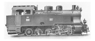
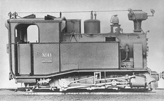
A Luttermöller axle is an unusual steam locomotive component. Steam locomotives with several axles or wheelsets connected to one another by coupling rods are not able to negotiate tight curves well. In order to assist such locomotives, the manager of the Orenstein & Koppel factory in Berlin, Dr. Luttermöller, built the axle system named after him.
The Saxon Class IX was a class of German, eight-coupled, tender locomotives built for the Royal Saxon State Railways for goods train duties.

The Saxon Class XV HTV was a class of goods train steam locomotive operated by the Royal Saxon State Railways, which had been conceived for hauling trains and acting as banking engines for routes in the Ore Mountains. In 1925 the Deutsche Reichsbahn grouped them into their DRG Class 79.0.

The Saxon Class V K were German 0-8-0T narrow gauge steam locomotives operated by the Royal Saxon State Railways which had been primarily intended for the Müglitztalbahn. In 1925 the Deutsche Reichsbahn incorporated arranged these locomotives as DRG Class 99.61.

The Gölsdorf axle system is used on railway Gölsdorf locomotives to achieve quiet running and low wear-and-tear when negotiating curves. The axle system comprises a combination of fixed axles and axles that can slide transversely, all within a single, rigid locomotive frame. The system was invented by a young Austrian locomotive builder, Karl Gölsdorf, around the end of the 19th century. The first locomotive to use this principle entered service in 1897.
A cannon bearing or cannon box bearing is an arrangement of bearings on a shaft, usually an axle, where two bearings are mounted in an enclosed tube.
The Saxon I K (one-K) were a class of German narrow-gauge 0-6-0T locomotives of the Royal Saxon State Railways with a track gauge of 750 mm. In 1925, Deutsche Reichsbahn grouped these locomotives into their DRG class 99.750–752.

MLR nos. 1-4 were four steam locomotives that operated on the Matheran Hill Railway, supplied by German engineering company Orenstein and Koppel. These locomotives served the railway from its inauguration in 1907, until 1982, when they were withdrawn from service, and completely replaced by diesel locomotives.


