
A steam locomotive is a locomotive that provides the force to move itself and other vehicles by means of the expansion of steam. It is fuelled by burning combustible material to heat water in the locomotive's boiler to the point where it becomes gaseous and its volume increases 1,700 times. Functionally, it is a steam engine on wheels.
As used in mechanical engineering, the term tractive force can either refer to the total traction a vehicle exerts on a surface, or the amount of the total traction that is parallel to the direction of motion.
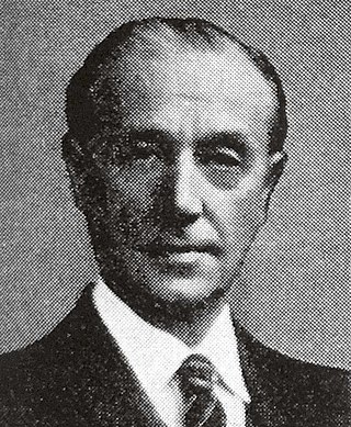
Oliver Vaughan Snell Bulleid CBE was a British railway and mechanical engineer best known as the Chief Mechanical Engineer (CME) of the Southern Railway between 1937 and the 1948 nationalisation, developing many well-known locomotives.

The valve gear of a steam engine is the mechanism that operates the inlet and exhaust valves to admit steam into the cylinder and allow exhaust steam to escape, respectively, at the correct points in the cycle. It can also serve as a reversing gear. It is sometimes referred to as the "motion".

The Walschaerts valve gear is a type of valve gear used to regulate the flow of steam to the pistons in steam locomotives, invented by Belgian railway engineer Egide Walschaerts in 1844. The gear is sometimes named without the final "s", since it was incorrectly patented under that name. It was extensively used in steam locomotives from the late 19th century until the end of the steam era.
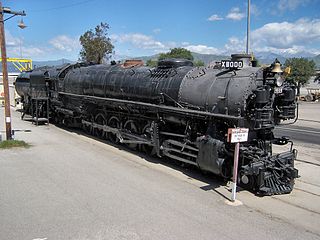
The Union Pacific Railroad 9000 Class was a class of 88 steam locomotives, built by ALCO for the Union Pacific between 1926 and 1930.

The SR West Country and Battle of Britain classes, collectively known as Light Pacifics or informally as Spam Cans, are air-smoothed 4-6-2 Pacific steam locomotives designed for the Southern Railway by its Chief Mechanical Engineer Oliver Bulleid. Incorporating a number of new developments in British steam locomotive technology, they were amongst the first British designs to use welding in the construction process, and to use steel fireboxes, which meant that components could be more easily constructed under wartime austerity and post-war economy.

The Gresley conjugated valve gear is a valve gear for steam locomotives designed by Sir Nigel Gresley, chief mechanical engineer of the LNER, assisted by Harold Holcroft. It enables a three-cylinder locomotive to operate with only the two sets of valve gear for the outside cylinders, and derives the valve motion for the inside cylinder from them by means of levers. The gear is sometimes known as the Gresley-Holcroft gear, acknowledging Holcroft's major contributions to its development.

The Stephenson valve gear or Stephenson link or shifting link is a simple design of valve gear that was widely used throughout the world for various kinds of steam engines. It is named after Robert Stephenson but was invented by his employees.

The Leader was a class of experimental 0-6-0+0-6-0T articulated steam locomotive, produced in the United Kingdom to the design of the innovative engineer Oliver Bulleid. The Leader was an attempt to extend the life of steam traction by eliminating many of the operational drawbacks associated with existing steam locomotives. It was intended as a replacement for the ageing fleet of M7 class tank engines still in operation on the Southern Railway (SR). Design work began in 1946 and development continued after the nationalisation of the railways in 1948, under the auspices of British Railways (BR).

The cylinder is the power-producing element of the steam engine powering a steam locomotive. The cylinder is made pressure-tight with end covers and a piston; a valve distributes the steam to the ends of the cylinder. Cylinders were cast in iron and later made of steel. The cylinder casting includes other features such as valve ports and mounting feet. The last big American locomotives incorporated the cylinders as part of huge one-piece steel castings that were the main frame of the locomotive. Renewable wearing surfaces were needed inside the cylinders and provided by cast-iron bushings.
Henry Greenly (1876–1947) was amongst the foremost miniature railway engineers of the 20th century, remembered as a master of engineering design.

The SECR N1 class was a type of 3-cylinder 2-6-0 ('mogul') steam locomotive designed by Richard Maunsell for mixed traffic duties, initially on the South Eastern and Chatham Railway (SECR), and later operated for the Southern Railway (SR). The N1 was a development of the basic principles established by the Great Western Railway's (GWR) Chief Mechanical Engineer (CME) George Jackson Churchward and by Maunsell's previous N class design.

Piston valves are one form of valve used to control the flow of steam within a steam engine or locomotive. They control the admission of steam into the cylinders and its subsequent exhausting, enabling a locomotive to move under its own power. The valve consists of two piston heads on a common spindle moving inside a steam chest, which is essentially a mini-cylinder located either above or below the main cylinders of the locomotive.

35006 Peninsular & Oriental S. N. Co. is a Southern Railway rebuilt Merchant Navy Class 4-6-2 steam locomotive. It was built at Eastleigh locomotive works in December 1941 and given the Southern Railway number 21C6. Although the first two members of the Merchant Navy class had their air-smoothed casings made of sheet steel, 21C6 was one of eight in which the casing was made of asbestos board, with a visible horizontal fixing strip along the centre line.

The SR Merchant Navy class is a class of air-smoothed 4-6-2 (Pacific) steam locomotives designed for the Southern Railway by Oliver Bulleid. The Pacific design was chosen in preference to several others proposed by Bulleid. The first members of the class were constructed during the Second World War, and the last of the 30 locomotives in 1949.
Córas Iompair Éireann No. CC1, generally known as the Turf Burner, was a prototype 0-6-6-0 articulated steam locomotive designed by Oliver Bulleid to burn turf and built at CIÉ's Inchicore Works in Dublin. CC1 shared some, but not all, of the characteristics of Bulleid's previous attempt to develop a modern steam locomotive, the Leader. Like the one completed Leader, CC1 had a relatively short career and was never used in front-line service. It was the last steam locomotive to be constructed for an Irish railway.
The South African Railways Class 16A 4-6-2 of 1915 was a steam locomotive.

A steam motor is a form of steam engine used for light locomotives and light self-propelled motor cars used on railways. The origins of steam motor cars for railways go back to at least the 1850s, if not earlier, as experimental economizations for railways or railroads with marginal budgets. These first examples, at least in North America, appear to have been fitted with light reciprocating engines, and either direct or geared drives, or geared-endless chain drives. Most incorporated a passenger carrying coach attached to the engine and its boiler. Boiler types varied in these earlier examples, with vertical boilers dominant in the first decade and then with very small diameter horizontal boilers. Other examples of steam motor cars incorporated an express-baggage or luggage type car body, with coupling apparatus provided to allow the steam motor car to draw a light passenger coach. An early example with the all-in-one was photographed working on the Nashville, Chattanooga & St. Louis Railroad during the American Civil War, in Tennessee, circa 1863-64. One American firm, Grice & Long, devised various versions in the mid-1860s for use on suburban and city street railways, using their proprietary mechanical patents. In the 1930s some highly evolved steam motors represented one of the final developments of the steam locomotive. The concurrent development of internal combustion-powered or electric-motored railway motor cars proved most popular circa 1900-1950s and those obviating the need for steam-powered cars.
The L&YR 2-10-0 was a prospective design for a class of 2-10-0 steam locomotives on the Lancashire and Yorkshire Railway. Initial designs were made by George Hughes between 1913–1914, but none of the class were built. If they had been, these would have been the UK's first 10-coupled locomotives in regular service.
