
The Stirling boiler is an early form of water-tube boiler, used to generate steam in large land-based stationary plants. Although widely used around 1900, it has now fallen from favour and is rarely seen.
The Stirling boiler is an early form of water-tube boiler, used to generate steam in large land-based stationary plants. Although widely used around 1900, it has now fallen from favour and is rarely seen.


Stirling boilers are one of the larger arrangements for a water-tube boiler: acceptable for stationary use, but impractical for mobile use, except for large ships with modest power requirements. They consist of a large brick-built chamber with a sinuous gas path through it, passing over near-vertical water-tubes that zig-zag between multiple steam drums and water drums.
They are amongst the older, "large-tube" designs of water-tube boilers, [1] having water-tubes that are around 3¼ inches (83 mm) in diameter. [2] The tubes are arranged in near-vertical banks between a number of cylindrical, horizontal steam drums (above) and water drums (below). The number of drums varies, and the Stirling designs are categorized into 3-, 4- and 5-drum boilers. The number of tube banks is one less than this, i.e. 2, 3 or 4 banks.
Gas flow from the furnace passes through each bank in turn. Partial baffles of firebrick tiles are laid on each bank, so as to force the gases to flow first up, and then down through each bank. Unusually, much of the gas flow is along the tubes' axis, rather than across them.
All circulation, both up and down, is through the heating tubes and there are no separate external downcomers. The steam drums and, (in a 5-drum boiler) the water drums, are however linked by short horizontal pipes and these form part of the circulation circuit.
The tubes themselves are seamless-drawn steel and mostly straight, with gently curved ends. [3] The setting of the boiler is a large brick-built enclosure, but the steam drums are suspended from a separate girder framework inside this, so as to allow for expansion with heat. The tubes, and the water drums in turn, are hung from the steam drums, again to allow free expansion without straining the tube ends. Owing to their curved ends the water-tubes may enter the drums radially, allowing easy sealing, but this was also a feature considered, according to the fashion of the time, to be important on account of expansion.
Stirling boilers may be made in very large sizes. It is usual for a standard design to be used, but in varying widths, according to need. [2]
Where a superheater is fitted, it is installed as straight or hairpin tubes in the upper part of the boiler between the first two steam drums. The baffles direct the gas-flow through this area first, so it may reach the highest temperature.
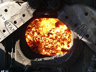
A wide range of fuels may be burned, aided by a large grate area that may easily be increased further, should a poor-quality fuel require it. The original boilers were developed to burn coal, but they have been used since to burn many sorts of wood or plant waste.
A chain-fed automatic stoker may also be fitted, where a heavy firing rate is required.
The three-drum form is also used as a heat-recovery boiler, using the exhaust gases from steelworks or other industrial processes. [2]
As the gas flow passes through each tube bank in turn, the later banks are at a significantly lower temperature. This encourages an "extremely efficient" circulation [3] by the thermosyphon effect. Water level is maintained with the steam drums approximately half-full, so the tubes operate in the "drowned" state with their upper ends permanently submerged.
Flow in the first bank is upwards as the tubes are heated, encouraged by their almost vertical position. Cooler water in the later water-tubes descends. Circulation is completed by the link pipes between the steam drums. [2] Circulation is more active in the earlier, hotter circuits.
In the four-drum form, circulation within the middle bank may be split between a descending circuit with the first bank and an ascending circuit with the following bank. [2]
Feedwater is supplied to the final steam drum and distributed via an internal trough. The cold feedwater descends slowly through the last tube bank and into the last water drum. [3]
Any precipitable deposits (colloquially, "mud") will emerge from solution in this circuit and accumulate in the final water drum. This keeps them away from the more active early tube banks, reducing the problems and inefficiencies of scale build-up within the major heating tubes. [2] Since the final water drum may also be used to catch the "mud" (i.e. a "mud collector"), it is sometimes known as a "mud drum".
There are three advantages to the Stirling design:

Although broadly similar, variations with different numbers of tube banks are produced.
This simpler form is mainly used for low powers, or for heat-recovery from other furnace gases.
This is the main form of the boiler and gives efficient results with economical construction. [2]
The marine version of the boiler is also of this form.
This is a more complex form, which uses an extra tube bank to gain efficiency. It is most popular for large installations, such as power stations, or where efficiency is most needed so as to gain the maximum heating from a limited fuel capacity.
Although generally a land-based boiler, the four-drum form was also used as a marine boiler, to power large ships. [4]
The brick-built setting was replaced with a box-like steel housing, lined with firebrick. The water-tube diameter was reduced to between 2 and 2+1⁄2 inches (50.8 and 63.5 mm). To avoid problems with the water levels shifting as the ship rolls, the water drums were arranged crosswise to the hull and provided with internal baffles.

A boiler is a closed vessel in which fluid is heated. The fluid does not necessarily boil. The heated or vaporized fluid exits the boiler for use in various processes or heating applications, including water heating, central heating, boiler-based power generation, cooking, and sanitation.

A fire-tube boiler is a type of boiler invented in 1828 by Mark Seguin, in which hot gases pass from a fire through one or more tubes running through a sealed container of water. The heat of the gases is transferred through the walls of the tubes by thermal conduction, heating the water and ultimately creating steam.

A high pressure watertube boiler is a type of boiler in which water circulates in tubes heated externally by fire. Fuel is burned inside the furnace, creating hot gas which boils water in the steam-generating tubes. In smaller boilers, additional generating tubes are separate in the furnace, while larger utility boilers rely on the water-filled tubes that make up the walls of the furnace to generate steam.
In a steam engine, the firebox is the area where the fuel is burned, producing heat to boil the water in the boiler. Most are somewhat box-shaped, hence the name. The hot gases generated in the firebox are pulled through a rack of tubes running through the boiler.

A thermal power station is a type of power station in which heat energy is converted to electrical energy. In a steam-generating cycle heat is used to boil water in a large pressure vessel to produce high-pressure steam, which drives a steam turbine connected to an electrical generator. The low-pressure exhaust from the turbine enters a steam condenser where it is cooled to produce hot condensate which is recycled to the heating process to generate more high pressure steam. This is known as a Rankine cycle.

The steam-electric power station is a power station in which the electric generator is steam driven. Water is heated, turns into steam and spins a steam turbine which drives an electrical generator. After it passes through the turbine, the steam is condensed in a condenser. The greatest variation in the design of steam-electric power plants is due to the different fuel sources.
Economizers, or economisers (UK), are mechanical devices intended to reduce energy consumption, or to perform useful function such as preheating a fluid. The term economizer is used for other purposes as well. Boiler, power plant, heating, refrigeration, ventilating, and air conditioning (HVAC) uses are discussed in this article. In simple terms, an economizer is a heat exchanger.

A boiler or steam generator is a device used to create steam by applying heat energy to water. Although the definitions are somewhat flexible, it can be said that older steam generators were commonly termed boilers and worked at low to medium pressure but, at pressures above this, it is more usual to speak of a steam generator.

A vertical boiler with horizontal fire-tubes is a type of small vertical boiler, used to generate steam for small machinery. It is characterised by having many narrow fire-tubes, running horizontally.

Yarrow boilers are an important class of high-pressure water-tube boilers. They were developed by Yarrow & Co. (London), Shipbuilders and Engineers and were widely used on ships, particularly warships.
Boilers for generating steam or hot water have been designed in countless shapes, sizes and configurations. An extensive terminology has evolved to describe their common features. This glossary provides definitions for these terms.
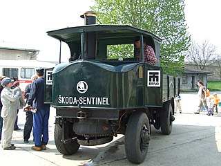
The Sentinel boiler was a design of vertical boiler, fitted to the numerous steam wagons built by the Sentinel Waggon Works.

Three-drum boilers are a class of water-tube boiler used to generate steam, typically to power ships. They are compact and of high evaporative power, factors that encourage this use. Other boiler designs may be more efficient, although bulkier, and so the three-drum pattern was rare as a land-based stationary boiler.

Spiral water-tube boilers are a family of vertical water-tube boilers. Their steam generating tubes are narrow spiral tubes, arranged in circular fashion around a central vertical water drum.

An evaporator, distiller or distilling apparatus is a piece of ship's equipment used to produce fresh drinking water from sea water by distillation. As fresh water is bulky, may spoil in storage, and is an essential supply for any long voyage, the ability to produce more fresh water in mid-ocean is important for any ship.

A steam generator is a form of low water-content boiler, similar to a flash steam boiler. The usual construction is as a spiral coil of water-tube, arranged as a single, or monotube, coil. Circulation is once-through and pumped under pressure, as a forced-circulation boiler. The narrow-tube construction, without any large-diameter drums or tanks, means that they are safe from the effects of explosion, even if worked at high pressures. The pump flowrate is adjustable, according to the quantity of steam required at that time. The burner output is throttled to maintain a constant working temperature. The burner output required varies according to the quantity of water being evaporated: this can be either adjusted by open-loop control according to the pump throughput, or by a closed-loop control to maintain the measured temperature.
A cornertube boiler is a type of natural circulation water-tube boiler which differentiates itself from other water tube boilers by its characteristic water-steam cycle and a pre-separation of heated steam from the steam-water mixture occurs outside the drum and the unheated downcomers.

A thimble tube boiler is a form of steam boiler, usually provided as an auxiliary boiler or heat-recovery boiler. They are vertical in orientation and would be considered a form of water-tube boiler.

The Reed water tube boiler was a type of water tube boiler developed by J. W. Reed, manager of the engine works at Palmers Shipbuilding and Iron Company of Jarrow, England, where it was manufactured from 1893 to 1905. At this time, Palmers was a vertically integrated business: in its shipyard at Jarrow, using iron ore from its own mine in North Yorkshire, it produced the iron and steel needed for its ships, and engines and boilers of its own design.