A steam turbine or steam turbine engine is a machine or heat engine that extracts thermal energy from pressurized steam and uses it to do mechanical work utilising a rotating output shaft. Its modern manifestation was invented by Sir Charles Parsons in 1884.[1][2] It revolutionized marine propulsion and navigation to a significant extent. Fabrication of a modern steam turbine involves advanced metalwork to form high-grade steel alloys into precision parts using technologies that first became available in the 20th century; continued advances in durability and efficiency of steam turbines remains central to the energy economics of the 21st century. The largest steam turbine ever built is the 1,770 MW Arabelle steam turbine built by Arabelle Solutions (previously GE Steam Power), two units of which will be installed at Hinkley Point C Nuclear Power Station, England.[3][4]
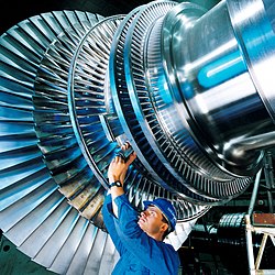
A 250kW industrial steam turbine from 1910 (right) directly linked to a generator (left)
The first device that may be classified as a reaction steam turbine was little more than a toy, the classic Aeolipile, described in the 1st century by Hero of Alexandria in Roman Egypt.[6][7] In 1551, Taqi al-Din in Ottoman Egypt described a steam turbine with the practical application of rotating a spit. Steam turbines were also described by the Italian Giovanni Branca (1629)[8] and John Wilkins in England (1648).[9][10] The devices described by Taqi al-Din and Wilkins are today known as steam jacks. In 1672, an impulse turbine-driven small toy car was designed by Ferdinand Verbiest. A more modern version of this car was produced some time in the late 18th century by an unknown German mechanic. In 1775, at Soho James Watt designed a reaction turbine that was put to work there.[11] In 1807, Polikarp Zalesov designed and constructed an impulse turbine, using it for the fire pump operation.[12] In 1827, the Frenchmen Real and Pichon patented and constructed a compound impulse turbine.[13]
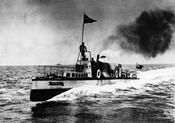
The first steam turbine-powered ship Turbinia: fastest in the world in 1894
The modern steam turbine was invented in 1884 by Charles Parsons, whose first model was connected to a dynamo that generated 7.5 kilowatts (10.1hp) of electricity.[14] The invention of Parsons' steam turbine made cheap and plentiful electricity possible and revolutionized marine transport and naval warfare.[15] Parsons' design was a reaction type. His patent was licensed and the turbine scaled up shortly after by an American, George Westinghouse. The Parsons turbine also turned out to be easy to scale up. Parsons had the satisfaction of seeing his invention adopted for all major world power stations, and the size of generators had increased from his first 7.5 kilowatts (10.1hp) set up to units of 50,000 kilowatts (67,000hp) capacity. Within Parsons' lifetime, the generating capacity of a unit was scaled up by about 10,000 times,[16] and the total output from turbo-generators constructed by his firm C. A. Parsons and Company and by their licensees, for land purposes alone, had exceeded thirty million horse-power.[14]
Other variations of turbines have been developed that work effectively with steam. The de Laval turbine (invented by Gustaf de Laval) accelerated the steam to full speed before running it against a turbine blade. De Laval's impulse turbine is simpler and less expensive and does not need to be pressure-proof. It can operate with any pressure of steam, but is considerably less efficient.[citation needed]Auguste Rateau developed a pressure compounded impulse turbine using the de Laval principle as early as 1896,[17] obtained a US patent in 1903, and applied the turbine to a French torpedo boat in 1904. He taught at the École des mines de Saint-Étienne for a decade until 1897, and later founded a successful company that was incorporated into the Alstom firm after his death. One of the founders of the modern theory of steam and gas turbines was Aurel Stodola, a Slovak physicist and engineer and professor at the Swiss Polytechnical Institute (now ETH) in Zurich. His work Die Dampfturbinen und ihre Aussichten als Wärmekraftmaschinen (English: The Steam Turbine and its prospective use as a Heat Engine) was published in Berlin in 1903. A further book Dampf und Gas-Turbinen (English: Steam and Gas Turbines) was published in 1922.[18]
The Brown-Curtis turbine, an impulse type, which had been originally developed and patented by the U.S. company International Curtis Marine Turbine Company, was developed in the 1900s in conjunction with John Brown & Company. It was used in John Brown-engined merchant ships and warships, including liners and Royal Navy warships.
Manufacturing
A steam turbine without its top cover
The present-day manufacturing industry for steam turbines consists of the following companies:[19][20]
Steam turbines are made in a variety of sizes ranging from small <0.75kW (<1hp) units (rare) used as mechanical drives for pumps, compressors and other shaft driven equipment, to 1,500MW (2,000,000hp) turbines used to generate electricity. There are several classifications for modern steam turbines.
Blade and stage design
Schematic diagram outlining the difference between an impulse and a 50% reaction turbine
Turbine blades are of two basic types, blades and nozzles. Blades move entirely due to the impact of steam on them and their profiles do not converge. This results in a steam velocity drop and essentially no pressure drop as steam moves through the blades. A turbine composed of blades alternating with fixed nozzles is called an impulse turbine, Curtis turbine, Rateau turbine, or Brown-Curtis turbine. Nozzles appear similar to blades, but their profiles converge near the exit. This results in a steam pressure drop and velocity increase as steam moves through the nozzles. Nozzles move due to both the impact of steam on them and the reaction due to the high-velocity steam at the exit. A turbine composed of moving nozzles alternating with fixed nozzles is called a reaction turbine or Parsons turbine.
Except for low-power applications, turbine blades are arranged in multiple stages in series, called compounding, which greatly improves efficiency at low speeds.[21] A reaction stage is a row of fixed nozzles followed by a row of moving nozzles. Multiple reaction stages divide the pressure drop between the steam inlet and exhaust into numerous small drops, resulting in a pressure-compounded turbine. Impulse stages may be either pressure-compounded, velocity-compounded, or pressure-velocity compounded. A pressure-compounded impulse stage is a row of fixed nozzles followed by a row of moving blades, with multiple stages for compounding. This is also known as a Rateau turbine, after its inventor. A velocity-compounded impulse stage (invented by Curtis and also called a "Curtis wheel") is a row of fixed nozzles followed by two or more rows of moving blades alternating with rows of fixed blades. This divides the velocity drop across the stage into several smaller drops.[22] A series of velocity-compounded impulse stages is called a pressure-velocity compounded turbine.
Diagram of an AEG marine steam turbine circa 1905
By 1905, when steam turbines were coming into use on fast ships (such as HMSDreadnought) and in land-based power applications, it had been determined that it was desirable to use one or more Curtis wheels at the beginning of a multi-stage turbine (where the steam pressure is highest), followed by reaction stages. This was more efficient with high-pressure steam due to reduced leakage between the turbine rotor and the casing.[23] This is illustrated in the drawing of the German 1905 AEG marine steam turbine. The steam from the boilers enters from the right at high pressure through a throttle, controlled manually by an operator (in this case a sailor known as the throttleman). It passes through five Curtis wheels and numerous reaction stages (the small blades at the edges of the two large rotors in the middle) before exiting at low pressure, almost certainly to a condenser. The condenser provides a vacuum that maximizes the energy extracted from the steam, and condenses the steam into feedwater to be returned to the boilers. On the left are several additional reaction stages (on two large rotors) that rotate the turbine in reverse for astern operation, with steam admitted by a separate throttle. Since ships are rarely operated in reverse, efficiency is not a priority in astern turbines, so only a few stages are used to save cost.
Blade design challenges
A major challenge facing turbine design was reducing the creep experienced by the blades. Because of the high temperatures and high stresses of operation, steam turbine materials become damaged through these mechanisms. As temperatures are increased in an effort to improve turbine efficiency, creep becomes significant. To limit creep, thermal coatings and superalloys with solid-solution strengthening and grain boundary strengthening are used in blade designs.
Protective coatings are used to reduce the thermal damage and to limit oxidation. These coatings are often stabilized zirconium dioxide-based ceramics. Using a thermal protective coating limits the temperature exposure of the nickel superalloy. This reduces the creep mechanisms experienced in the blade. Oxidation coatings limit efficiency losses caused by a buildup on the outside of the blades, which is especially important in the high-temperature environment.[24]
The nickel-based blades are alloyed with aluminum and titanium to improve strength and creep resistance. The microstructure of these alloys is composed of different regions of composition. A uniform dispersion of the gamma-prime phase – a combination of nickel, aluminum, and titanium – promotes the strength and creep resistance of the blade due to the microstructure.[25]
Refractory elements such as rhenium and ruthenium can be added to the alloy to improve creep strength. The addition of these elements reduces the diffusion of the gamma prime phase, thus preserving the fatigue resistance, strength, and creep resistance.[26]
Steam supply and exhaust conditions
A low-pressure steam turbine in a nuclear power plant. These turbines exhaust steam at a pressure below atmospheric.
Turbine types include condensing, non-condensing, reheat, extracting and induction.
Condensing turbines
Condensing turbines are most commonly found in electrical power plants. These turbines receive steam from a boiler and exhaust it to a condenser. The exhausted steam is at a pressure well below atmospheric, and is in a partially condensed state, typically of a quality near 90%.
Non-condensing turbines
Non-condensing turbines are most widely used for process steam applications, in which the steam will be used for additional purposes after being exhausted from the turbine. The exhaust pressure is controlled by a regulating valve to suit the needs of the process steam pressure. These are commonly found at refineries, district heating units, pulp and paper plants, and desalination facilities where large amounts of low pressure process steam are needed.
Reheat turbines
Reheat turbines are also used almost exclusively in electrical power plants. In a reheat turbine, steam flow exits from a high-pressure section of the turbine and is returned to the boiler where additional superheat is added. The steam then goes back into an intermediate pressure section of the turbine and continues its expansion. Using reheat in a cycle increases the work output from the turbine and also the expansion reaches conclusion before the steam condenses, thereby minimizing the erosion of the blades in last rows. In most of the cases, maximum number of reheats employed in a cycle is 2 as the cost of super-heating the steam negates the increase in the work output from turbine.
Extracting turbines
Extracting type turbines are common in all applications. In an extracting type turbine, steam is released from various stages of the turbine, and used for industrial process needs or sent to boiler feedwater heaters to improve overall cycle efficiency. Extraction flows may be controlled with a valve, or left uncontrolled. Extracted steam results in a loss of power in the downstream stages of the turbine.
Induction turbines introduce low pressure steam at an intermediate stage to produce additional power.
Casing or shaft arrangements
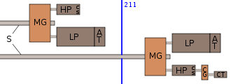
These arrangements include single casing, tandem compound and cross compound turbines. Single casing units are the most basic style where a single casing and shaft are coupled to a generator. Tandem compound are used where two or more casings are directly coupled together to drive a single generator. A cross compound turbine arrangement features two or more shafts not in line driving two or more generators that often operate at different speeds. A cross compound turbine is typically used for many large applications. A typical 1930s-1960s naval installation is illustrated below; this shows high- and low-pressure turbines driving a common reduction gear, with a geared cruising turbine on one high-pressure turbine.
Starboard steam turbine machinery arrangement of Japanese Furutaka- and Aoba-class cruisers
Two-flow rotors
A two-flow turbine rotor. The steam enters in the middle of the shaft, and exits at each end, balancing the axial force.
The moving steam imparts both a tangential and axial thrust on the turbine shaft, but the axial thrust in a simple turbine is unopposed. To maintain the correct rotor position and balancing, this force must be counteracted by an opposing force. Thrust bearings can be used for the shaft bearings, the rotor can use dummy pistons, it can be double flow- the steam enters in the middle of the shaft and exits at both ends, or a combination of any of these. In a double flow rotor, the blades in each half face opposite ways, so that the axial forces negate each other but the tangential forces act together. This design of rotor is also called two-flow, double-axial-flow, or double-exhaust. This arrangement is common in low-pressure casings of a compound turbine.[27]
Principle of operation and design
An ideal steam turbine is considered to be an isentropic process, or constant entropy process, in which the entropy of the steam entering the turbine is equal to the entropy of the steam leaving the turbine. No steam turbine is truly isentropic, however, with typical isentropic efficiencies ranging from 20 to 90% based on the application of the turbine. The interior of a turbine comprises several sets of blades or buckets. One set of stationary blades is connected to the casing and one set of rotating blades is connected to the shaft. The sets intermesh with certain minimum clearances, with the size and configuration of sets varying to efficiently exploit the expansion of steam at each stage.
Impulse turbines
A selection of impulse turbine blades
An impulse turbine has fixed nozzles that orient the steam flow into high speed jets. These jets contain significant kinetic energy, which is converted into shaft rotation by the bucket-like shaped rotor blades, as the steam jet changes direction. A pressure drop occurs across only the stationary blades, with a net increase in steam velocity across the stage. As the steam flows through the nozzle its pressure falls from inlet pressure to the exit pressure (atmospheric pressure or, more usually, the condenser vacuum). Due to this high ratio of expansion of steam, the steam leaves the nozzle with a very high velocity. The steam leaving the moving blades has a large portion of the maximum velocity of the steam when leaving the nozzle. The loss of energy due to this higher exit velocity is commonly called the carry over velocity or leaving loss.
The law of moment of momentum states that the sum of the moments of external forces acting on a fluid which is temporarily occupying the control volume is equal to the net time change of angular momentum flux through the control volume.
The swirling fluid enters the control volume at radius with tangential velocity and leaves at radius with tangential velocity .
Velocity triangle
A velocity triangle paves the way for a better understanding of the relationship between the various velocities. In the adjacent figure we have:
and are the absolute velocities at the inlet and outlet respectively.
and are the flow velocities at the inlet and outlet respectively.
and are the swirl velocities at the inlet and outlet respectively, in the moving reference.
and are the relative velocities at the inlet and outlet respectively.
is the velocity of the blade.
is the guide vane angle and is the blade angle.
Then by the law of moment of momentum, the torque on the fluid is given by:
For an impulse steam turbine: . Therefore, the tangential force on the blades is . The work done per unit time or power developed: .
When ω is the angular velocity of the turbine, then the blade speed is . The power developed is then .
Blade efficiency
Blade efficiency () can be defined as the ratio of the work done on the blades to kinetic energy supplied to the fluid, and is given by
A stage of an impulse turbine consists of a nozzle set and a moving wheel. The stage efficiency defines a relationship between enthalpy drop in the nozzle and work done in the stage. Where is the specific enthalpy drop of steam in the nozzle.
By the first law of thermodynamics: Assuming that is appreciably less than , we get . Furthermore, stage efficiency is the product of blade efficiency and nozzle efficiency, or .
Nozzle efficiency is given by , where the enthalpy (in J/Kg) of steam at the entrance of the nozzle is and the enthalpy of steam at the exit of the nozzle is . The ratio of the cosines of the blade angles at the outlet and inlet can be taken and denoted . The ratio of steam velocities relative to the rotor speed at the outlet to the inlet of the blade is defined by the friction coefficient .
and depicts the loss in the relative velocity due to friction as the steam flows around the blades ( for smooth blades).
The ratio of the blade speed to the absolute steam velocity at the inlet is termed the blade speed ratio .
is maximum when or, . That implies and therefore . Now (for a single stage impulse turbine).
Therefore, the maximum value of stage efficiency is obtained by putting the value of in the expression of .
We get: .
For equiangular blades, , therefore , and we get . If the friction due to the blade surface is neglected then .
Conclusions on maximum efficiency
For a given steam velocity work done per kg of steam would be maximum when or .
As increases, the work done on the blades reduces, but at the same time surface area of the blade reduces, therefore there are less frictional losses.
Reaction turbines
In the reaction turbine, the rotor blades themselves are arranged to form convergent nozzles. This type of turbine makes use of the reaction force produced as the steam accelerates through the nozzles formed by the stator. Steam is directed onto the rotor by the fixed vanes of the stator. It leaves the stator as a jet that fills the entire circumference of the rotor. The steam then changes direction and increases its speed relative to the speed of the blades. A pressure drop occurs across both the stator and the rotor, with steam accelerating through the stator and decelerating through the rotor, with no net change in steam velocity across the stage but with a decrease in both pressure and temperature, reflecting the work performed in the driving of the rotor.
Blade efficiency
Energy input to the blades in a stage:
is equal to the kinetic energy supplied to the fixed blades (f) + the kinetic energy supplied to the moving blades (m).
Or, = enthalpy drop over the fixed blades, + enthalpy drop over the moving blades, .
The effect of expansion of steam over the moving blades is to increase the relative velocity at the exit. Therefore, the relative velocity at the exit is always greater than the relative velocity at the inlet .
In terms of velocities, the enthalpy drop over the moving blades is given by: (it contributes to a change in static pressure)
Velocity diagram
The enthalpy drop in the fixed blades, with the assumption that the velocity of steam entering the fixed blades is equal to the velocity of steam leaving the previously moving blades is given by: where V0 is the inlet velocity of steam in the nozzle
is very small and hence can be neglected. Therefore,
A very widely used design has half degree of reaction or 50% reaction and this is known as Parson's turbine. This consists of symmetrical rotor and stator blades. For this turbine the velocity triangle is similar and we have: , ,
Assuming Parson's turbine and obtaining all the expressions we get From the inlet velocity triangle we have Work done (for unit mass flow per second):
Therefore, the blade efficiency is given by
Condition of maximum blade efficiency
Comparing Efficiencies of Impulse and Reaction turbines
If , then
For maximum efficiency , we get
and this finally gives
Therefore, is found by putting the value of in the expression of blade efficiency
Operation and maintenance
A modern steam turbine generator setup
Steam turbines and their casings have a high thermal inertia due to the high pressures used in steam circuits and the materials used. When warming up a set for use, the main steam stop valves (after the boiler) have a bypass line to allow superheated steam to slowly bypass the valve and proceed to heat up the lines in the system along with the steam turbine. In addition, when there is no steam, a turning gear is engaged to slowly rotate the turbine to ensure even heating and prevent uneven expansion. After first rotating the turbine by the turning gear, allowing time for the rotor to assume a straight plane (no bowing), then the turning gear is disengaged and steam is admitted to the turbine, first to the astern blades then to the ahead blades slowly rotating the turbine at 10–15RPM (0.17–0.25Hz) to slowly warm the turbine. The warm-up procedure for large steam turbines may exceed ten hours.[28]
During normal operation, rotor imbalance can lead to vibration, which, because of the high rotation velocities, could lead to a blade breaking away from the rotor and through the casing. To mitigate this risk, significant efforts are made to balance the turbine. Also, turbines are run with high-quality steam: either superheated (dry) steam, or saturated steam with a high dryness fraction. This prevents the rapid impingement and erosion of the blades which occurs when condensed water is blasted onto the blades (moisture carry over). Also, liquid water entering the blades may damage the thrust bearings for the turbine shaft. To prevent this, along with controls and baffles in the boilers to ensure high-quality steam, condensate drains are installed in the steam piping leading to the turbine.
Maintenance requirements of modern steam turbines are simple and incur low costs (typically around $0.005 per kWh);[28] their operational life often exceeds 50 years.
Speed regulation
Diagram of a steam turbine generator system
The control of a turbine with a governor is essential, as turbines need to be run up slowly to prevent damage and some applications (such as the generation of alternating current electricity) require precise speed control.[29] Uncontrolled acceleration of the turbine rotor can lead to an overspeed trip, which causes the governor and throttle valves that control the flow of steam to the turbine to close. If these valves fail then the turbine may continue accelerating until it breaks apart, often catastrophically. Turbines are expensive to make, requiring precision manufacture and special quality materials.
During normal operation in synchronization with the electricity network, power plants are governed with a five percent droop speed control. This means the full load speed is 100% and the no-load speed is 105%. This is required for the stable operation of the network without hunting and drop-outs of power plants. Normally the changes in speed are minor. Adjustments in power output are made by slowly raising the droop curve by increasing the spring pressure on a centrifugal governor. Generally this is a basic system requirement for all power plants because the older and newer plants have to be compatible in response to the instantaneous changes in frequency without depending on outside communication.[30]
The steam turbine operates on basic principles of thermodynamics using the part 3-4 of the Rankine cycle shown in the adjoining diagram. Superheated steam (or dry saturated steam, depending on application) leaves the boiler at high temperature and high pressure. At entry to the turbine, the steam gains kinetic energy by passing through a nozzle (a fixed nozzle in an impulse type turbine or the fixed blades in a reaction type turbine). When the steam leaves the nozzle it is moving at high velocity towards the blades of the turbine rotor. A force is created on the blades due to the pressure of the vapor on the blades causing them to move. A generator or other such device can be placed on the shaft, and the energy that was in the steam can now be stored and used. The steam leaves the turbine as a saturated vapor (or liquid-vapor mix depending on application) at a lower temperature and pressure than it entered with and is sent to the condenser to be cooled.[31] The first law enables us to find a formula for the rate at which work is developed per unit mass. Assuming there is no heat transfer to the surrounding environment and that the changes in kinetic and potential energy are negligible compared to the change in specific enthalpy we arrive at the following equation:
where
is the rate at which work is developed per unit time
is the rate of mass flow through the turbine
Isentropic efficiency
To measure how well a turbine is performing we can look at its isentropic efficiency. This compares the actual performance of the turbine with the performance that would be achieved by an ideal, isentropic, turbine.[32] When calculating this efficiency, heat lost to the surroundings is assumed to be zero. Steam's starting pressure and temperature is the same for both the actual and the ideal turbines, but at turbine exit, steam's energy content ('specific enthalpy') for the actual turbine is greater than that for the ideal turbine because of irreversibility in the actual turbine. The specific enthalpy is evaluated at the same steam pressure for the actual and ideal turbines in order to give a good comparison between the two.
The isentropic efficiency is found by dividing the actual work by the ideal work.[32]
where
h3 is the specific enthalpy at state three
h4 is the specific enthalpy at state 4 for the actual turbine
h4s is the specific enthalpy at state 4s for the isentropic turbine
(but note that the adjacent diagram does not show state 4s: it is vertically below state 3)
The turbines used for electric power generation are most often directly coupled to their generators. As the generators must rotate at constant synchronous speeds according to the frequency of the electric power system, the most common speeds are 3,000RPM for 50Hz systems, and 3,600RPM for 60Hz systems. Since nuclear reactors have lower temperature limits than fossil-fired plants, with lower steam quality, the turbine generator sets may be arranged to operate at half these speeds, but with four-pole generators, to reduce erosion of turbine blades.[34]
Marine propulsion
"Turbine Steam Ship" redirects here. For other uses, see TS (disambiguation).
Turbinia, 1894, the first steam turbine-powered shipHigh and low pressure turbines for SSMauiParsons turbine from the 1928 Polish destroyer Wicher
In steamships, advantages of steam turbines over reciprocating engines are smaller size, lower maintenance, lighter weight, and lower vibration. A steam turbine is efficient only when operating in the thousands of RPM, while the most effective propeller designs are for speeds less than 300 RPM; consequently, precise (thus expensive) reduction gears are usually required, although numerous early ships through World War I, such as Turbinia, had direct drive from the steam turbines to the propeller shafts. Another alternative is turbo-electric transmission, in which an electrical generator run by the high-speed turbine is used to run one or more slow-speed electric motors connected to the propeller shafts; precision gear cutting may be a production bottleneck during wartime. Turbo-electric drive was most used in large US warships designed during World War I and in some fast liners, and was used in some troop transports and mass-production destroyer escorts in World War II.
The higher cost of turbines and the associated gears or generator/motor sets is offset by lower maintenance requirements and the smaller size of a turbine in comparison with a reciprocating engine of equal power, although the fuel costs are higher than those of a diesel engine because steam turbines have lower thermal efficiency. To reduce fuel costs the thermal efficiency of both types of engine have been improved over the years.
Early development
The development of steam turbine marine propulsion from 1894 to 1935 was dominated by the need to reconcile the high efficient speed of the turbine with the low efficient speed (less than 300 rpm) of the ship's propeller at an overall cost competitive with reciprocating engines. In 1894, efficient reduction gears were not available for the high powers required by ships, so direct drive was necessary. In Turbinia, which has direct drive to each propeller shaft, the efficient speed of the turbine was reduced after initial trials by directing the steam flow through all three direct drive turbines (one on each shaft) in series, probably totaling around 200 turbine stages operating in series. Also, there were three propellers on each shaft for operation at high speeds.[35] The high shaft speeds of the era are represented by one of the first US turbine-powered destroyers, USSSmith, launched in 1909, which had direct drive turbines and whose three shafts turned at 724 rpm at 28.35 knots (52.50km/h; 32.62mph).[36]
The use of turbines in several casings exhausting steam to each other in series became standard in most subsequent marine propulsion applications, and is a form of cross-compounding. The first turbine was called the high pressure (HP) turbine, the last turbine was the low pressure (LP) turbine, and any turbine in between was an intermediate pressure (IP) turbine. A much later arrangement than Turbinia can be seen on RMSQueen Mary in Long Beach, California, launched in 1934, in which each shaft is powered by four turbines in series connected to the ends of the two input shafts of a single-reduction gearbox. They are the HP, 1st IP, 2nd IP, and LP turbines.
Cruising machinery and gearing
The quest for economy was even more important when cruising speeds were considered. Cruising speed is roughly 50% of a warship's maximum speed and 20-25% of its maximum power level. This would be a speed used on long voyages when fuel economy is desired. Although this brought the propeller speeds down to an efficient range, turbine efficiency was greatly reduced, and early turbine ships had poor cruising ranges. A solution that proved useful through most of the steam turbine propulsion era was the cruising turbine. This was an extra turbine to add even more stages, at first attached directly to one or more shafts, exhausting to a stage partway along the HP turbine, and not used at high speeds. As reduction gears became available around 1911, some ships, notably the battleshipUSSNevada, had them on cruising turbines while retaining direct drive main turbines. Reduction gears allowed turbines to operate in their efficient range at a much higher speed than the shaft, but were expensive to manufacture.
Cruising turbines competed at first with reciprocating engines for fuel economy. An example of the retention of reciprocating engines on fast ships was the famous RMSOlympic of 1911, which along with her sisters RMSTitanic and HMHSBritannic had triple-expansion engines on the two outboard shafts, both exhausting to an LP turbine on the center shaft. After adopting turbines with the Delaware-class battleships launched in 1909, the United States Navy reverted to reciprocating machinery on the New York-class battleships of 1912, then went back to turbines on Nevada in 1914. The lingering fondness for reciprocating machinery was because the US Navy had no plans for capital ships exceeding 21 knots (39km/h; 24mph) until after World War I, so top speed was less important than economical cruising. The United States had acquired the Philippines and Hawaii as territories in 1898, and lacked the British Royal Navy's worldwide network of coaling stations. Thus, the US Navy in 1900–1940 had the greatest need of any nation for fuel economy, especially as the prospect of war with Japan arose following World War I. This need was compounded by the US not launching any cruisers 1908–1920, so destroyers were required to perform long-range missions usually assigned to cruisers. So, various cruising solutions were fitted on US destroyers launched 1908–1916. These included small reciprocating engines and geared or ungeared cruising turbines on one or two shafts. However, once fully geared turbines proved economical in initial cost and fuel they were rapidly adopted, with cruising turbines also included on most ships. Beginning in 1915 all new Royal Navy destroyers had fully geared turbines, and the United States followed in 1917.
In the Royal Navy, speed was a priority until the Battle of Jutland in mid-1916 showed that in the battlecruisers too much armour had been sacrificed in its pursuit. The British used exclusively turbine-powered warships from 1906. Because they recognized that a long cruising range would be desirable given their worldwide empire, some warships, notably the Queen Elizabeth-class battleships, were fitted with cruising turbines from 1912 onwards following earlier experimental installations.
In the US Navy, the Mahan-class destroyers, launched 1935–36, introduced double-reduction gearing. This further increased the turbine speed above the shaft speed, allowing smaller turbines than single-reduction gearing. Steam pressures and temperatures were also increasing progressively, from 300psi (2,100kPa)/425°F (218°C) [saturated steam] on the World War I-era Wickes class to 615psi (4,240kPa)/850°F (454°C) [superheated steam] on some World War II Fletcher-class destroyers and later ships.[37][38] A standard configuration emerged of an axial-flow high-pressure turbine (sometimes with a cruising turbine attached) and a double-axial-flow low-pressure turbine connected to a double-reduction gearbox. This arrangement continued throughout the steam era in the US Navy and was also used in some Royal Navy designs.[39][40] Machinery of this configuration can be seen on many preserved World War II-era warships in several countries.[41]
When US Navy warship construction resumed in the early 1950s, most surface combatants and aircraft carriers used 1,200psi (8,300kPa)/950°F (510°C) steam.[42] This continued until the end of the US Navy steam-powered warship era with the Knox-classfrigates of the early 1970s. Amphibious and auxiliary ships continued to use 600psi (4,100kPa) steam post-World War II, with USSIwo Jima, launched in 2001, possibly the last non-nuclear steam-powered ship built for the US Navy.
Turbo-electric drive
NS50 Let Pobedy, a nuclear icebreaker with nuclear-turbo-electric propulsion
Turbo-electric drive was introduced on the battleship USSNew Mexico, launched in 1917. Over the next eight years the US Navy launched five additional turbo-electric-powered battleships and two aircraft carriers (initially ordered as Lexington-class battlecruisers). Ten more turbo-electric capital ships were planned, but cancelled due to the limits imposed by the Washington Naval Treaty.
Although New Mexico was refitted with geared turbines in a 1931–1933 refit, the remaining turbo-electric ships retained the system throughout their careers. This system used two large steam turbine generators to drive an electric motor on each of four shafts. The system was less costly initially than reduction gears and made the ships more maneuverable in port, with the shafts able to reverse rapidly and deliver more reverse power than with most geared systems.
Some ocean liners were also built with turbo-electric drive, as were some troop transports and mass-production destroyer escorts in World War II. However, when the US designed the "treaty cruisers", beginning with USSPensacola launched in 1927, geared turbines were used to conserve weight, and remained in use for all fast steam-powered ships thereafter.
Today, propulsion steam turbine cycle efficiencies have yet to break 50%, yet diesel engines routinely exceed 50%, especially in marine applications.[44][45][46] Diesel power plants also have lower operating costs since fewer operators are required. Thus, conventional steam power is used in very few new ships. An exception is LNG carriers which often find it more economical to use boil-off gas with a steam turbine than to re-liquify it.
Nuclear power is often chosen where diesel power would be impractical (as in submarine applications) or the logistics of refuelling pose significant problems (for example, icebreakers). It has been estimated that the reactor fuel for the Royal Navy's Vanguard-class submarines is sufficient to last 40 circumnavigations of the globe – potentially sufficient for the vessel's entire service life. Nuclear propulsion has only been applied to a very few commercial vessels due to the expense of maintenance and the regulatory controls required on nuclear systems and fuel cycles.
A steam turbine locomotive engine is a steam locomotive driven by a steam turbine. The first steam turbine rail locomotive was built in 1908 for the Officine Meccaniche Miani Silvestri Grodona Comi, Milan, Italy. In 1924 Krupp built the steam turbine locomotive T18 001, operational in 1929, for Deutsche Reichsbahn.
The main advantages of a steam turbine locomotive are better rotational balance and reduced hammer blow on the track. However, a disadvantage is less flexible output power so that turbine locomotives were best suited for long-haul operations at a constant output power.[47]
Testing
British, German, other national and international test codes are used to standardize the procedures and definitions used to test steam turbines. Selection of the test code to be used is an agreement between the purchaser and the manufacturer, and has some significance to the design of the turbine and associated systems.
In the United States, ASME has produced several performance test codes on steam turbines. These include ASME PTC 6–2004, Steam Turbines, ASME PTC 6.2-2011, Steam Turbines in Combined Cycles, PTC 6S-1988, Procedures for Routine Performance Test of Steam Turbines. These ASME performance test codes have gained international recognition and acceptance for testing steam turbines. The single most important and differentiating characteristic of ASME performance test codes, including PTC 6, is that the test uncertainty of the measurement indicates the quality of the test and is not to be used as a commercial tolerance.[48]
↑Takaishi, Tatsuo; Numata, Akira; Nakano, Ryouji; Sakaguchi, Katsuhiko (March 2008). "Approach to High Efficiency Diesel and Gas Engines"(PDF). Technical Review. Mitsubishi Heavy Industries. Retrieved 6 May 2019.
Latief, Fahamsyah H; Kakehi, Koji (2013). "Effects of Re content and crystallographic orientation on creep behavior of aluminized Ni-base single crystal superalloys". Materials & Design. 49: 485–492. doi:10.1016/j.matdes.2013.01.022. ISSN0261-3069.
Johnston, Ian (2019). "The Rise of the Brown-Curtis Turbine". In Jordan, John (ed.). Warship 2019. Oxford: Osprey Publishing. pp.58–68. ISBN978-1-4728-3595-6.
Traupel, W (1977). Thermische Turbomaschinen (in German). Springer Verlag: Berlin, Heidelberg, New York.
Waliullah, Noushad (2017). "An overview of Concentrated Solar Power (CSP) technologies and its opportunities in Bangladesh". 2017 International Conference on Electrical, Computer and Communication Engineering (ECCE). CUET. pp.844–849. doi:10.1109/ECACE.2017.7913020. ISBN978-1-5090-5627-9. S2CID42153522.
This page is based on this Wikipedia article Text is available under the CC BY-SA 4.0 license; additional terms may apply. Images, videos and audio are available under their respective licenses.