
In thermodynamics and engineering, a heat engine is a system that converts heat to usable energy, particularly mechanical energy, which can then be used to do mechanical work. While originally conceived in the context of mechanical energy, the concept of the heat engine has been applied to various other kinds of energy, particularly electrical, since at least the late 19th century. The heat engine does this by bringing a working substance from a higher state temperature to a lower state temperature. A heat source generates thermal energy that brings the working substance to the higher temperature state. The working substance generates work in the working body of the engine while transferring heat to the colder sink until it reaches a lower temperature state. During this process some of the thermal energy is converted into work by exploiting the properties of the working substance. The working substance can be any system with a non-zero heat capacity, but it usually is a gas or liquid. During this process, some heat is normally lost to the surroundings and is not converted to work. Also, some energy is unusable because of friction and drag.

A pump is a device that moves fluids, or sometimes slurries, by mechanical action, typically converted from electrical energy into hydraulic energy.

A reciprocating engine, also often known as a piston engine, is typically a heat engine that uses one or more reciprocating pistons to convert high temperature and high pressure into a rotating motion. This article describes the common features of all types. The main types are: the internal combustion engine, used extensively in motor vehicles; the steam engine, the mainstay of the Industrial Revolution; and the Stirling engine for niche applications. Internal combustion engines are further classified in two ways: either a spark-ignition (SI) engine, where the spark plug initiates the combustion; or a compression-ignition (CI) engine, where the air within the cylinder is compressed, thus heating it, so that the heated air ignites fuel that is injected then or earlier.

A steam engine is a heat engine that performs mechanical work using steam as its working fluid. The steam engine uses the force produced by steam pressure to push a piston back and forth inside a cylinder. This pushing force can be transformed, by a connecting rod and crank, into rotational force for work. The term "steam engine" is generally applied only to reciprocating engines as just described, not to the steam turbine. Steam engines are external combustion engines, where the working fluid is separated from the combustion products. The ideal thermodynamic cycle used to analyze this process is called the Rankine cycle. In general usage, the term steam engine can refer to either complete steam plants, such as railway steam locomotives and portable engines, or may refer to the piston or turbine machinery alone, as in the beam engine and stationary steam engine.

A boiler is a closed vessel in which fluid is heated. The fluid does not necessarily boil. The heated or vaporized fluid exits the boiler for use in various processes or heating applications, including water heating, central heating, boiler-based power generation, cooking, and sanitation.

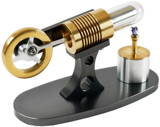
A Stirling engine is a heat engine that is operated by the cyclic compression and expansion of air or other gas between different temperatures, resulting in a net conversion of heat energy to mechanical work.

The Stirling cycle is a thermodynamic cycle that describes the general class of Stirling devices. This includes the original Stirling engine that was invented, developed and patented in 1816 by Robert Stirling with help from his brother, an engineer.
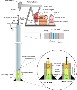
A pumpjack is the overground drive for a reciprocating piston pump in an oil well.
A refrigerator designed to reach cryogenic temperatures is often called a cryocooler. The term is most often used for smaller systems, typically table-top size, with input powers less than about 20 kW. Some can have input powers as low as 2–3 W. Large systems, such as those used for cooling the superconducting magnets in particle accelerators are more often called cryogenic refrigerators. Their input powers can be as high as 1 MW. In most cases cryocoolers use a cryogenic fluid as the working substance and employ moving parts to cycle the fluid around a thermodynamic cycle. The fluid is typically compressed at room temperature, precooled in a heat exchanger, then expanded at some low temperature. The returning low-pressure fluid passes through the heat exchanger to precool the high-pressure fluid before entering the compressor intake. The cycle is then repeated.
For fluid power, a working fluid is a gas or liquid that primarily transfers force, motion, or mechanical energy. In hydraulics, water or hydraulic fluid transfers force between hydraulic components such as hydraulic pumps, hydraulic cylinders, and hydraulic motors that are assembled into hydraulic machinery, hydraulic drive systems, etc. In pneumatics, the working fluid is air or another gas which transfers force between pneumatic components such as compressors, vacuum pumps, pneumatic cylinders, and pneumatic motors. In pneumatic systems, the working gas also stores energy because it is compressible.
The Ericsson cycle is named after inventor John Ericsson who designed and built many unique heat engines based on various thermodynamic cycles. He is credited with inventing two unique heat engine cycles and developing practical engines based on these cycles. His first cycle is now known as the closed Brayton cycle, while his second cycle is what is now called the Ericsson cycle. Ericsson is one of the few who built open-cycle engines, but he also built closed-cycle ones.

A hot air engine is any heat engine that uses the expansion and contraction of air under the influence of a temperature change to convert thermal energy into mechanical work. These engines may be based on a number of thermodynamic cycles encompassing both open cycle devices such as those of Sir George Cayley and John Ericsson and the closed cycle engine of Robert Stirling. Hot air engines are distinct from the better known internal combustion based engine and steam engine.
This timeline of heat engine technology describes how heat engines have been known since antiquity but have been made into increasingly useful devices since the 17th century as a better understanding of the processes involved was gained. A heat engine is any system that converts heat to mechanical energy, which can then be used to do mechanical work.They continue to be developed today.
Economizers, or economisers (UK), are mechanical devices intended to reduce energy consumption, or to perform useful function such as preheating a fluid. The term economizer is used for other purposes as well. Boiler, power plant, heating, refrigeration, ventilating, and air conditioning (HVAC) uses are discussed in this article. In simple terms, an economizer is a heat exchanger.
Engine efficiency of thermal engines is the relationship between the total energy contained in the fuel, and the amount of energy used to perform useful work. There are two classifications of thermal engines-
- Internal combustion and
- External combustion engines.
Thermodynamic heat pump cycles or refrigeration cycles are the conceptual and mathematical models for heat pump, air conditioning and refrigeration systems. A heat pump is a mechanical system that allows for the transmission of heat from one location at a lower temperature to another location at a higher temperature. Thus a heat pump may be thought of as a "heater" if the objective is to warm the heat sink, or a "refrigerator" or “cooler” if the objective is to cool the heat source. In either case, the operating principles are similar. Heat is moved from a cold place to a warm place.

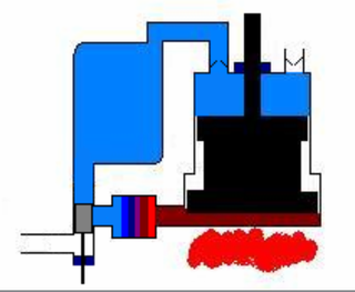
A vacuum engine derives its force from air pressure against one side of the piston, which has a partial vacuum on the other side of it. At the beginning of an outstroke, a valve in the head of the cylinder opens and admits a charge of burning gas and air, which is trapped by the closing of the valve and expands. Towards the end of the stroke the charge comes into contact with a water- or air-cooled part of the cylinder and is chilled, causing a sudden drop in pressure sufficient to suck the piston – which is open towards the crank – back on the return stroke. The valve opens again in time for the piston to expel the burnt gases before the next outstroke begins.
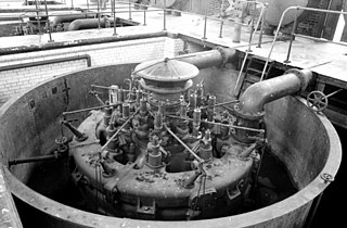
The Humphrey pump is a large internal combustion gas-fuelled liquid-piston pump. They were used for large-scale water supply projects. They were only popular for a short time, from around 1910 to the outbreak of World War I, but they continued in service for a long period afterwards, some lasting into the 1970s.
An internal combustion engine is a heat engine in which the combustion of a fuel occurs with an oxidizer in a combustion chamber that is an integral part of the working fluid flow circuit. In an internal combustion engine, the expansion of the high-temperature and high-pressure gases produced by combustion applies direct force to some component of the engine. The force is typically applied to pistons, turbine blades, a rotor, or a nozzle. This force moves the component over a distance, transforming chemical energy into kinetic energy which is used to propel, move or power whatever the engine is attached to.
A Manson-Guise engine is an improved version of a Manson engine. It is a type of hot air engine, converting a temperature difference into motion. There is a hot side and a cold side to the engine. Providing there is a large enough temperature difference between the two sides the engine will run. The Manson-Guise engine is probably the simplest type of hot air engines having only a single con-rod, with a displacer piston and power piston that move at the same time. Manson-Guise engines, like Manson engines and beta Stirling engines, can run bidirectionally.


