Timeline of heat engine technology

Last updated

This timeline of heat engine technology describes how heat engines have been known since antiquity but have been made into increasingly useful devices since the 17th century as a better understanding of the processes involved was gained. A heat engine is any system that converts heat to mechanical energy, which can then be used to do mechanical work.They continue to be developed today.

Contents

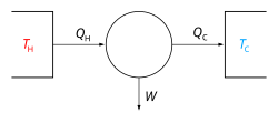
In engineering and thermodynamics, a heat engine performs the conversion of heat energy to mechanical work by exploiting the temperature gradient between a hot "source" and a cold "sink". Heat is transferred to the sink from the source, and in this process some of the heat is converted into work.

A heat pump is a heat engine run in reverse. Work is used to create a heat differential. The timeline includes devices classed as both engines and pumps, as well as identifying significant leaps in human understanding.

Pre-17th century

17th century

18th century

19th century

20th century

21st century

See also

Related timelines:

For a timeline of all human technology see:

Related Research Articles

<span class="mw-page-title-main">Engine</span> Machine that converts one or more forms of energy into mechanical energy (of motion)

An engine or motor is a machine designed to convert one or more forms of energy into mechanical energy.

<span class="mw-page-title-main">Heat engine</span> System that converts heat or thermal energy to mechanical work

A heat engine is a system that converts heat to usable energy, particularly mechanical energy, which can then be used to do mechanical work. While originally conceived in the context of mechanical energy, the concept of the heat engine has been applied to various other kinds of energy, particularly electrical, since at least the late 19th century. The heat engine does this by bringing a working substance from a higher state temperature to a lower state temperature. A heat source generates thermal energy that brings the working substance to the higher temperature state. The working substance generates work in the working body of the engine while transferring heat to the colder sink until it reaches a lower temperature state. During this process some of the thermal energy is converted into work by exploiting the properties of the working substance. The working substance can be any system with a non-zero heat capacity, but it usually is a gas or liquid. During this process, some heat is normally lost to the surroundings and is not converted to work. Also, some energy is unusable because of friction and drag.

<span class="mw-page-title-main">Reciprocating engine</span> Engine utilising one or more reciprocating pistons

A reciprocating engine, also often known as a piston engine, is typically a heat engine that uses one or more reciprocating pistons to convert high temperature and high pressure into a rotating motion. This article describes the common features of all types. The main types are: the internal combustion engine, used extensively in motor vehicles; the steam engine, the mainstay of the Industrial Revolution; and the Stirling engine for niche applications. Internal combustion engines are further classified in two ways: either a spark-ignition (SI) engine, where the spark plug initiates the combustion; or a compression-ignition (CI) engine, where the air within the cylinder is compressed, thus heating it, so that the heated air ignites fuel that is injected then or earlier.

<span class="mw-page-title-main">Steam engine</span> Engine that uses steam to perform mechanical work

A steam engine is a heat engine that performs mechanical work using steam as its working fluid. The steam engine uses the force produced by steam pressure to push a piston back and forth inside a cylinder. This pushing force can be transformed, by a connecting rod and crank, into rotational force for work. The term "steam engine" is most commonly applied to reciprocating engines as just described, although some authorities have also referred to the steam turbine and devices such as Hero's aeolipile as "steam engines". The essential feature of steam engines is that they are external combustion engines, where the working fluid is separated from the combustion products. The ideal thermodynamic cycle used to analyze this process is called the Rankine cycle. In general usage, the term steam engine can refer to either complete steam plants, such as railway steam locomotives and portable engines, or may refer to the piston or turbine machinery alone, as in the beam engine and stationary steam engine.

Timeline of motor and engine technology

<span class="mw-page-title-main">Otto cycle</span> Thermodynamic cycle for spark ignition piston engines

An Otto cycle is an idealized thermodynamic cycle that describes the functioning of a typical spark ignition piston engine. It is the thermodynamic cycle most commonly found in automobile engines.

<span class="mw-page-title-main">Four-stroke engine</span> Internal combustion engine type

A four-strokeengine is an internal combustion (IC) engine in which the piston completes four separate strokes while turning the crankshaft. A stroke refers to the full travel of the piston along the cylinder, in either direction. The four separate strokes are termed:

  1. Intake: Also known as induction or suction. This stroke of the piston begins at top dead center (T.D.C.) and ends at bottom dead center (B.D.C.). In this stroke the intake valve must be in the open position while the piston pulls an air-fuel mixture into the cylinder by producing a partial vacuum in the cylinder through its downward motion.
  2. Compression: This stroke begins at B.D.C, or just at the end of the suction stroke, and ends at T.D.C. In this stroke the piston compresses the air-fuel mixture in preparation for ignition during the power stroke (below). Both the intake and exhaust valves are closed during this stage.
  3. Combustion: Also known as power or ignition. This is the start of the second revolution of the four stroke cycle. At this point the crankshaft has completed a full 360 degree revolution. While the piston is at T.D.C. the compressed air-fuel mixture is ignited by a spark plug or by heat generated by high compression, forcefully returning the piston to B.D.C. This stroke produces mechanical work from the engine to turn the crankshaft.
  4. Exhaust: Also known as outlet. During the exhaust stroke, the piston, once again, returns from B.D.C. to T.D.C. while the exhaust valve is open. This action expels the spent air-fuel mixture through the exhaust port.
<span class="mw-page-title-main">Stirling engine</span> Closed-cycle regenerative heat engine

A Stirling engine is a heat engine that is operated by the cyclic compression and expansion of air or other gas between different temperatures, resulting in a net conversion of heat energy to mechanical work.

<span class="mw-page-title-main">Brayton cycle</span> Thermodynamic cycle

The Brayton cycle, also known as the Joule cycle, is a thermodynamic cycle that describes the operation of certain heat engines that have air or some other gas as their working fluid. It is characterized by isentropic compression and expansion, and isobaric heat addition and rejection, though practical engines have adiabatic rather than isentropic steps.

<span class="mw-page-title-main">Compressor</span> Machine to increase pressure of gas by reducing its volume

A compressor is a mechanical device that increases the pressure of a gas by reducing its volume. An air compressor is a specific type of gas compressor.

For fluid power, a working fluid is a gas or liquid that primarily transfers force, motion, or mechanical energy. In hydraulics, water or hydraulic fluid transfers force between hydraulic components such as hydraulic pumps, hydraulic cylinders, and hydraulic motors that are assembled into hydraulic machinery, hydraulic drive systems, etc. In pneumatics, the working fluid is air or another gas which transfers force between pneumatic components such as compressors, vacuum pumps, pneumatic cylinders, and pneumatic motors. In pneumatic systems, the working gas also stores energy because it is compressible.

<span class="mw-page-title-main">Ericsson cycle</span> Type of thermodynamic cycle

The Ericsson cycle is named after inventor John Ericsson who designed and built many unique heat engines based on various thermodynamic cycles. He is credited with inventing two unique heat engine cycles and developing practical engines based on these cycles. His first cycle is now known as the closed Brayton cycle, while his second cycle is what is now called the Ericsson cycle. Ericsson is one of the few who built open-cycle engines, but he also built closed-cycle ones.

<span class="mw-page-title-main">Hot air engine</span> External combustion engine using air as the working fluid

A hot air engine is any heat engine that uses the expansion and contraction of air under the influence of a temperature change to convert thermal energy into mechanical work. These engines may be based on a number of thermodynamic cycles encompassing both open cycle devices such as those of Sir George Cayley and John Ericsson and the closed cycle engine of Robert Stirling. Hot air engines are distinct from the better known internal combustion based engine and steam engine.

<span class="mw-page-title-main">Turbomachinery</span> Machine for exchanging energy with a fluid

Turbomachinery, in mechanical engineering, describes machines that transfer energy between a rotor and a fluid, including both turbines and compressors. While a turbine transfers energy from a fluid to a rotor, a compressor transfers energy from a rotor to a fluid. It is an important application of fluid mechanics.

<span class="mw-page-title-main">Thermal efficiency</span> Performance measure of a device that uses thermal energy

In thermodynamics, the thermal efficiency is a dimensionless performance measure of a device that uses thermal energy, such as an internal combustion engine, steam turbine, steam engine, boiler, furnace, refrigerator, ACs etc.

Engine efficiency of thermal engines is the relationship between the total energy contained in the fuel, and the amount of energy used to perform useful work. There are two classifications of thermal engines-

  1. Internal combustion and
  2. External combustion engines.
<span class="mw-page-title-main">Free-piston engine</span>

A free-piston engine is a linear, 'crankless' internal combustion engine, in which the piston motion is not controlled by a crankshaft but determined by the interaction of forces from the combustion chamber gases, a rebound device and a load device.

A liquid nitrogen vehicle is powered by liquid nitrogen, which is stored in a tank. Traditional nitrogen engine designs work by heating the liquid nitrogen in a heat exchanger, extracting heat from the ambient air and using the resulting pressurized gas to operate a piston or rotary motor. Vehicles propelled by liquid nitrogen have been demonstrated, but are not used commercially. One such vehicle, Liquid Air, was demonstrated in 1902.

Internal combustion engines come in a wide variety of types, but have certain family resemblances, and thus share many common types of components.

<span class="mw-page-title-main">Internal combustion engine</span> Engine in which the combustion of a fuel occurs with an oxidizer in a combustion chamber

An internal combustion engine is a heat engine in which the combustion of a fuel occurs with an oxidizer in a combustion chamber that is an integral part of the working fluid flow circuit. In an internal combustion engine, the expansion of the high-temperature and high-pressure gases produced by combustion applies direct force to some component of the engine. The force is typically applied to pistons, turbine blades, a rotor, or a nozzle. This force moves the component over a distance, transforming chemical energy into kinetic energy which is used to propel, move or power whatever the engine is attached to.

References

Citations

  1. Hellemans, Alexander; et al. (1991). ""The Timetables of Science: A Chronology of the Most Important People and Events in the History of Science"". New York: Touchstone/Simon & Schuster, Inc., 1991.
  2. Hero (1851) [reprint of 1st century CE original], "Section 50 – The Steam Engine". Translated from the original Greek by Bennet Woodcroft (Professor of Machinery in University College London.
  3. Needham, Joseph (1986), Science & Civilisation in China, V:7: The Gunpowder Epic, Cambridge University Press, ISBN   0-521-30358-3
  4. 1 2 Reid, Hugo (1838). The Steam-engine: Being a Popular Description of the Construction and Action of that Engine; with a Sketch of Its History, and of the Laws of Heat and Pneumatics. Edinburgh: William Tait. p.  74.
  5. Thurston, Robert Henry (1996). A History of the Growth of the Steam-Engine (reprint ed.). Elibron. p. 12. ISBN   1-4021-6205-7.
  6. Hassan, Ahmad Y. "Taqi al-Din and the First Steam Turbine". History of Science and Technology in Islam. Archived from the original on 2008-02-18. Retrieved 2008-03-29.
  7. Lardner, Dionysius (1840). The Steam Engine Explained and Illustrated. Taylor and Walton. p.  22. Full title: Le Machine volume nuovo, et di molto artificio da fare effetti maravigliosi tanto Spiritali quanto di Animale Operatione, arichito di bellissime figure. Del Sig. Giovanni Branco, Cittadino Romano. In Roma, 1629
  8. R. Boyle, A Defence of the Doctrine Touching the Spring and Weight of the Air, … (London: Thomas Robinson, 1662). Available on-line at: Spain's La Biblioteca Virtual de Patrimonio Bibliográfico. Boyle presents his law in "Chap. V. Two new experiments touching the measure of the force of the spring of air compress'd and dilated.", pp. 57–68. On p. 59, Boyle concludes that " … the same air being brought to a degree of density about twice as that it had before, obtains a spring twice as strong as formerly." That is, doubling the density of a quantity of air doubles its pressure. Since air's density is proportional to its pressure, then for a fixed quantity of air, the product of its pressure and its volume is constant. On page 60, he presents his data on the compression of air: "A Table of the Condensation of the Air." The legend (p. 60) accompanying the table states: "E. What the pressure should be according to the Hypothesis, that supposes the pressures and expansions to be in reciprocal relation." On p. 64, Boyle presents his data on the expansion of air: "A Table of the Rarefaction of the Air."https://bvpb.mcu.es/en/consulta/registro.cmd?id=406806
  9. The Century of Inventions, written in 1655; by Edward Somerset, Marquis of Worcester. Being a verbatim reprint of the first edition, published in 1663. Archived 21 February 2006 at the Wayback Machine archive https://web.archive.org/web/20060221151830/http://www.history.rochester.edu/steam/dircks/
  10. "The History of the Automobile – Gas Engines". About.com. 2009-09-11. Archived from the original on July 11, 2012. Retrieved 2009-10-19.
  11. The Griffin Engineering Company, of Bath, Somerset Archived 2007-05-13 at the Wayback Machine University Of Bath, 15 December 2004. Accessed May 2011
  12. Rasor, N. S. (1983). "Thermionic Energy Converter". In Chang, Sheldon S. L. (ed.). Fundamentals Handbook of Electrical and Computer Engineering. Vol. II. New York: Wiley. p. 668. ISBN   0-471-86213-4.
  13. Shoichi Toyabe; Takahiro Sagawa; Masahito Ueda; Eiro Muneyuki; Masaki Sano (2010-09-29). "Information heat engine: converting information to energy by feedback control". Nature Physics. 6 (12): 988–992. arXiv : 1009.5287. Bibcode : 2011NatPh...6..988T. doi : 10.1038/nphys1821. We demonstrated that free energy is obtained by a feedback control using the information about the system; information is converted to free energy, as the first realization of Szilard-type Maxwell’s demon.
  14. Michigan State University: Wave Disk Engine U.S. Department of Energy, Advanced Research Projects Agency, March 2011
  15. "The experimental demonstration of a spin quantum heat engine". phys.org. Retrieved 2020-01-01.
  16. "New quantum nanodevice can simultaneously act as a heat engine and a refrigerator". phys.org. Retrieved 2020-12-29.

Sources