Two intermeshing spur gears rotating at different velocity due to differing gear ratio
A gear[1][2] or gearwheel,[3][4][5] also called a toothed wheel, is a rotatingmachine part typically used to transmit rotational motion or torque by means of a series of "teeth" that engage with compatible teeth of another gear or other part. The teeth can be integral saliences or cavities machined on the part, or separate pegs inserted into it. In the latter case, the gear is usually called a cogwheel. A cog may be one of those pegs[6][7][8] or the whole gear.[9][6][8] Two or more meshing gears are called a gear train.
The smaller member of a pair of meshing gears is often called pinion. Most commonly, gears and gear trains can be used to trade torque for rotational speed between two axles or other rotating parts or to change the axis of rotation or to invert the sense of rotation. A gear may also be used to transmit linear force or linear motion to a rack, a straight bar with a row of compatible teeth.
Gears are among the most common mechanical parts. They come in a great variety of shapes and materials, and are used for many different functions and applications. Diameters may range from a few μm in micromachines,[10] to a few mm in watches and toys to over 10 metres in some mining equipment.[11] Other types of parts that are somewhat similar in shape and function to gears include the sprocket, which is meant to engage with a link chain instead of another gear, and the timing pulley, meant to engage a timing belt. Most gears are round and have equal teeth, designed to operate as smoothly as possible; but there are several applications for non-circular gears, and the Geneva drive has an extremely uneven operation, by design.
Gears can be seen as instances of the basic lever "machine".[12] When a small gear drives a larger one, the mechanical advantage of this ideal lever causes the torque T to increase but the rotational speedω to decrease. The opposite effect is obtained when a large gear drives a small one. The changes are proportional to the gear ratior, the ratio of the tooth counts: namely, T2/T1 = r = N2/N1, and ω2/ω1 = 1/r = N1/N2. Depending on the geometry of the pair, the sense of rotation may also be inverted (from clockwise to anti-clockwise, or vice versa).
Most vehicles have a transmission or "gearbox" containing a set of gears that can be meshed in multiple configurations. The gearbox lets the operator vary the torque that is applied to the wheels without changing the engine's speed. Gearboxes are used also in many other machines, such as lathes and conveyor belts. In all those cases, terms like "first gear", "high gear", and "reverse gear" refer to the overall torque ratios of different meshing configurations, rather than to specific physical gears. These terms may be applied even when the vehicle does not actually contain gears, as in a continuously variable transmission.[13]
History
The oldest functioning gears by far are not man made, but are seen in the hind legs of the nymphs of the planthopper insect Issus coleoptratus.
The earliest man-made gears that have not been lost or destroyed date to 4th century BC China[14] (Zhan Guo times – Late East Zhou dynasty), which have been preserved at the Luoyang Museum of Henan Province, China.
In Europe, Aristotle mentions gears around 330BC, as wheel drives in windlasses. He observed that the direction of rotation is reversed when one gear wheel drives another gear wheel. Philon of Byzantium was one of the first who used gears in water raising devices.[15] Gears appear in works connected to Hero of Alexandria, in Roman Egypt circa AD50,[16] but can be traced back to the mechanics of the Library of Alexandria in 3rd-century BC Ptolemaic Egypt, and were greatly developed by the Greek polymathArchimedes (287–212 BC).[17] The earliest surviving gears in Europe were found in the Antikythera mechanism an example of a very early and intricate geared device, designed to calculate astronomical positions of the sun, moon, and planets, and predict eclipses. Its time of construction is now estimated between 150 and 100BC.[18][19][20]
Modern model of a south-pointing chariot
The Chinese engineer Ma Jun (c.200–265) described a south-pointing chariot. A set of differential gears connected to the wheels and to a pointer on top of the chariot kept the direction of latter unchanged as the chariot turned.[21]
Another early surviving example of geared mechanism is a complex calendrical device showing the phase of the Moon, the day of the month and the places of the Sun and the Moon in the Zodiac was invented in the Byzantine empire in the early 6th century.[22][23]
Around 1221, a geared astrolabe was built in Isfahan showing the position of the moon in the zodiac and its phase, and the number of days since new moon.[24]
A complex astronomical clock, called the Astrarium, was built between 1348 and 1364 by Giovanni Dondi dell'Orologio. It had seven faces and 107 moving parts; it showed the positions of the sun, the moon and the five planets then known, as well as religious feast days.[26] The Salisbury Cathedral clock, built in 1386, it is the world's oldest still working geared mechanical clock.
The word gear is probably from Old Norsegørvi (plural gørvar) 'apparel, gear,' related to gøra, gørva 'to make, construct, build; set in order, prepare,' a common verb in Old Norse, "used in a wide range of situations from writing a book to dressing meat". In this context, the meaning of 'toothed wheel in machinery' first attested 1520s; specific mechanical sense of 'parts by which a motor communicates motion' is from 1814; specifically of a vehicle (bicycle, automobile, etc.) by 1888.[27]
A cog is a tooth on a wheel. From Middle English cogge, from Old Norse (compare Norwegiankugg ('cog'), Swedishkugg, kugge ('cog, tooth')), from Proto-Germanic *kuggō (compare Dutchkogge ('cog boat'), GermanKock), from Proto-Indo-European *gugā ('hump, ball') (compare Lithuaniangugà ('pommel, hump, hill'), from PIE *gēw- ('to bend, arch').[28] First used c. 1300 in the sense of 'a wheel having teeth or cogs; late 14c., 'tooth on a wheel'; cog-wheel, early 15c.[29]
Materials
Wooden cogwheel driving a lantern pinion or cage gear
The gears of the Antikythera mechanism are made of bronze, and the earliest surviving Chinese gears are made of iron. These metals, as well as tin, have been generally used for clocks and similar mechanisms to this day.
Historically, large gears, such as those used in flour mills, were commonly made of wood rather than metal. They were cogwheels, made by inserting a series of wooden pegs or cogs around the rim of a wheel. The cogs were often made of maple wood.
Wooden gears have been gradually replaced by ones made or metal, such as cast iron at first, then steel and aluminum. Steel is most commonly used because of its high strength-to-weight ratio and low cost. Aluminum is not as strong as steel for the same geometry, but is lighter and easier to machine. Powder metallurgy may be used with alloys that cannot be easily cast or machined.
A cast gearwheel (above) meshing with a cogged mortise wheel (below). The wooden cogs are held in place by nails.
Still, because of cost or other considerations, some early metal gears had wooden cogs, each tooth forming a type of specialised 'through' mortise and tenon joint[30]
More recently engineering plastics and composite materials have been replacing metals in many applications, especially those with moderate speed and torque. They are not as strong as steel, but are cheaper, can be mass-manufactured by injection molding,[31] and do not need lubrication. Plastic gears can even be intentionally designed to be the weakest part in a mechanism, so that in case of jamming they will fail first and thus avoid damage to more expensive parts. Such "sacrificial" gears may be a simpler alternative to other overload-protection devices such as clutches and torque-limited or current-limited motors.
In spite of the advantages of metal and plastic, wood continued to be used for large gears until a couple of centuries ago, because of cost, weight, tradition, or other considerations. In 1967 the Thompson Manufacturing Company of Lancaster, New Hampshire still had a very active business in supplying tens of thousands of maple gear teeth per year, mostly for use in paper mills and grist mills, some dating back over 100 years.[32]
As of 2014, an estimated 80% of all gearing produced worldwide is produced by net shape molding. Molded gearing is usually powder metallurgy, plastic injection, or metal die casting.[33] Gears produced by powder metallurgy often require a sintering step after they are removed from the mold. Cast gears require gear cutting or other machining to shape the teeth to the necessary precision. The most common form of gear cutting is hobbing, but gear shaping, milling, and broaching may be used instead.
Metal gears intended for heavy duty operation, such as in the transmissions of cars and trucks, the teeth are heat treated to make them hard and more wear resistant while leaving the core soft but tough. For large gears that are prone to warp, a quench press is used.
Gears can be made by 3D printing; however, this alternative is typically used only for prototypes or very limited production quantities, because of its high cost, low accuracy, and relatively low strength of the resulting part.
One major advantage of gears is that their rigid body and the snug interlocking of the teeth ensure precise tracking of the rotation across the gear train, limited only by backlash and other mechanical defects. For this reason they are favored in precision applications such as watches. Gear trains also can have fewer separate parts (only two) and have minimal power loss, minimal wear, and long life. Gears are also often the most efficient and compact way of transmitting torque between two non-parallel axes.
On the other hand, gears are more expensive to manufacture, may require periodic lubrication, and may have greater mass and rotational inertia than the equivalent pulleys. More importantly, the distance between the axes of matched gears is limited and cannot be changed once they are manufactured. There are also applications where slippage under overload or transients (as occurs with belts, hydraulics, and friction wheels) is not only acceptable but desirable.
Ideal gear model
For basic analysis purposes, each gear can be idealized as a perfectly rigid body that, in normal operation, turns around a rotation axis that is fixed in space, without sliding along it. Thus, each point of the gear can move only along a circle that is perpendicular to its axis and centered on it. At any moment t, all points of the gear will be rotating around that axis with the same angular speedω(t), in the same sense. The speed need not be constant over time.
The action surface of the gear consists of all points of its surface that, in normal operation, may contact the matching gear with positive pressure. All other parts of the surface are irrelevant (except that they cannot be crossed by any part of the matching gear). In a gear with N teeth, the working surface has N-fold rotational symmetry about the axis, meaning that it is congruent with itself when the gear rotates by 1/N of a turn.
If the gear is meant to transmit or receive torque with a definite sense only (clockwise or counterclockwise with respect to some reference viewpoint), the action surface consists of N separate patches, the tooth faces; which have the same shape and are positioned in the same way relative to the axis, spaced 1/N turn apart.
If the torque on each gear may have both senses, the action surface will have two sets of N tooth faces; each set will be effective only while the torque has one specific sense, and the two sets can be analyzed independently of the other. However, in this case the gear usually has also "flip over" symmetry, so that the two sets of tooth faces are congruent after the gear is flipped. This arrangement ensures that the two gears are firmly locked together, at all times, with no backlash.
During operation, each point p of each tooth face will at some moment contact a tooth face of the matching gear at some point q of one of its tooth faces. At that moment and at those points, the two faces must have the same perpendicular direction but opposite orientation. But since the two gears are rotating around different axes, the points p and q are moving along different circles; therefore, the contact cannot last more than one instant, and p will then either slide across the other face, or stop contacting it altogether.
On the other hand, at any given moment there is at least one such pair of contact points; usually more than one, even a whole line or surface of contact.
Actual gears deviate from this model in many ways: they are not perfectly rigid, their mounting does not ensure that the rotation axis will be perfectly fixed in space, the teeth may have slightly different shapes and spacing, the tooth faces are not perfectly smooth, and so on. Yet, these deviations from the ideal model can be ignored for a basic analysis of the operation of a gear set.
Relative axis position
One criterion for classifying gears is the relative position and direction of the axes or rotation of the gears that are to be meshed together.
Parallel
In the most common configuration, the axes of rotation of the two gears are parallel, and usually their sizes are such that they contact near a point between the two axes. In this configuration, the two gears turn in opposite senses.
Occasionally the axes are parallel but one gear is nested inside the other. In this configuration, both gears turn in the same sense.
If the two gears are cut by an imaginary plane perpendicular to the axes, each section of one gear will interact only with the corresponding section of the other gear. Thus the three-dimensional gear train can be understood as a stack of gears that are flat and infinitesimally thin — that is, essentially two-dimensional.
In a crossed arrangement, the axes of rotation of the two gears are not parallel but cross at an arbitrary angle except zero or 180 degrees.
For best operation, each wheel then must be a bevel gear, whose overall shape is like a slice (frustum) of a cone whose apex is the meeting point of the two axes.
Bevel gears with equal numbers of teeth and shaft axes at 90 degrees are called miter (US) or mitre (UK) gears.
Independently of the angle between the axes, the larger of two unequal matching bevel gears may be internal or external, depending the desired relative sense of rotation.[34]
If the two gears are sliced by an imaginary sphere whose center is the point where the two axes cross, each section will remain on the surface of that sphere as the gear rotates, and the section of one gear will interact only with the corresponding section of the other gear. In this way, a pair of meshed 3D gears can be understood as a stack of nested infinitely thin cup-like gears.
Skew
Hypoid gear
The gears in a matching pair are said to be skew if their axes of rotation are skew lines -- neither parallel nor intersecting.
In this case, the best shape for each pitch surface is neither cylindrical nor conical but a portion of a hyperboloid of revolution.[35][36] Such gears are called hypoid for short. Hypoid gears are most commonly found with shafts at 90 degrees.
Contact between hypoid gear teeth may be even smoother and more gradual than with spiral bevel gear teeth, but also have a sliding action along the meshing teeth as it rotates and therefore usually require some of the most viscous types of gear oil to avoid it being extruded from the mating tooth faces, the oil is normally designated HP (for hypoid) followed by a number denoting the viscosity. Also, the pinion can be designed with fewer teeth than a spiral bevel pinion, with the result that gear ratios of 60:1 and higher are feasible using a single set of hypoid gears.[37] This style of gear is most common in motor vehicle drive trains, in concert with a differential. Whereas a regular (non hypoid) ring-and-pinion gear set is suitable for many applications, it is not ideal for vehicle drive trains because it generates more noise and vibration than a hypoid does. Bringing hypoid gears to market for mass-production applications was an engineering improvement of the 1920s.
Tooth orientation
Internal and external
Internal gearCrown gear
A gear is said to be external if its teeth are directed generally away from the rotation axis, and internal otherwise.[34] In a pair of matching wheels, only one of them (the larger one) may be internal.
Crown
A crown gear or contrate gear is one whose teeth project at right angles to the plane. A crown gear is also sometimes meshed with an escapement such as found in mechanical clocks.
Tooth cut direction
Gear teeth typically extend across the whole thickness of the gear. Another criterion for classifying gears is the general direction of the teeth across that dimension. This attribute is affected by the relative position and direction of the axes or rotation of the gears that are to be meshed together.
Straight
Spur gear
In a cylindrical spur gear or straight-cut gear, the tooth faces are straight along the direction parallel to the axis of rotation. Any imaginary cylinder with the same axis will cut the teeth along parallel straight lines.
The teeth can be either internal or external. Two spur gears mesh together correctly only if fitted to parallel shafts.[38] No axial thrust is created by the tooth loads. Spur gears are excellent at moderate speeds but tend to be noisy at high speeds.[39]
For arrangements with crossed non-parallel axes, the faces in a straight-cut gear are parts of a general conical surface whose generating lines (generatrices) go through the meeting point of the two axes, resulting in a bevel gear. Such gears are generally used only at speeds below 5m/s (980ft/min), or, for small gears, 1000 rpm.[40]
In a helical or dry fixed gear the tooth walls are not parallel to the axis of rotation, but are set at an angle. An imaginary pitch surface (cylinder, cone, or hyperboloid, depending on the relative axis positions) intersects each tooth face along an arc of a helix. Helical gears can be meshed in either parallel or crossed orientations. The former refers to when the shafts are parallel to each other; this is the most common orientation. In the latter, the shafts are non-parallel, and in this configuration the gears are sometimes known as "skew gears".
An external contact helical gear in action
The angled teeth engage more gradually than do spur gear teeth, causing them to run more smoothly and quietly.[41] With parallel helical gears, each pair of teeth first make contact at a single point at one side of the gear wheel; a moving curve of contact then grows gradually across the tooth face to a maximum, then recedes until the teeth break contact at a single point on the opposite side. In spur gears, teeth suddenly meet at a line contact across their entire width, causing stress and noise. Spur gears make a characteristic whine at high speeds. For this reason spur gears are used in low-speed applications and in situations where noise control is not a problem, and helical gears are used in high-speed applications, large power transmission, or where noise abatement is important.[42] The speed is considered high when the pitch line velocity exceeds 25m/s.[43]
A disadvantage of helical gears is a resultant thrust along the axis of the gear, which must be accommodated by appropriate thrust bearings. However, this issue can be circumvented by using a herringbone gear or double helical gear, which has no axial thrust - and also provides self-aligning of the gears. This results in less axial thrust than a comparable spur gear.
A second disadvantage of helical gears is a greater degree of sliding friction between the meshing teeth, often addressed with additives in the lubricant.
For a "crossed" or "skew" configuration, the gears must have the same pressure angle and normal pitch; however, the helix angle and handedness can be different. The relationship between the two shafts is actually defined by the helix angle(s) of the two shafts and the handedness, as defined:[44]
for gears of the same handedness,
for gears of opposite handedness,
where is the helix angle for the gear. The crossed configuration is less mechanically sound because there is only a point contact between the gears, whereas in the parallel configuration there is a line contact.[44]
Quite commonly, helical gears are used with the helix angle of one having the negative of the helix angle of the other; such a pair might also be referred to as having a right-handed helix and a left-handed helix of equal angles. The two equal but opposite angles add to zero: the angle between shafts is zero—that is, the shafts are parallel. Where the sum or the difference (as described in the equations above) is not zero, the shafts are crossed. For shafts crossed at right angles, the helix angles are of the same hand because they must add to 90 degrees. (This is the case with the gears in the illustration above: they mesh correctly in the crossed configuration: for the parallel configuration, one of the helix angles should be reversed. The gears illustrated cannot mesh with the shafts parallel.)
Double helical gears overcome the problem of axial thrust presented by single helical gears by using a double set of teeth, slanted in opposite directions. A double helical gear can be thought of as two mirrored helical gears mounted closely together on a common axle. This arrangement cancels out the net axial thrust, since each half of the gear thrusts in the opposite direction, resulting in a net axial force of zero. This arrangement can also remove the need for thrust bearings. However, double helical gears are more difficult to manufacture due to their more complicated shape.
Herringbone gears are a special type of helical gears. They do not have a groove in the middle like some other double helical gears do; the two mirrored helical gears are joined so that their teeth form a V shape. This can also be applied to bevel gears, as in the final drive of the Citroën Type A. Another type of double helical gear is a Wüst gear.
For both possible rotational directions, there exist two possible arrangements for the oppositely oriented helical gears or gear faces. One arrangement is called stable, and the other unstable. In a stable arrangement, the helical gear faces are oriented so that each axial force is directed toward the center of the gear. In an unstable arrangement, both axial forces are directed away from the center of the gear. In either arrangement, the total (or net) axial force on each gear is zero when the gears are aligned correctly. If the gears become misaligned in the axial direction, the unstable arrangement generates a net force that may lead to disassembly of the gear train, while the stable arrangement generates a net corrective force. If the direction of rotation is reversed, the direction of the axial thrusts is also reversed, so a stable configuration becomes unstable, and vice versa.
Stable double helical gears can be directly interchanged with spur gears without any need for different bearings.
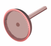
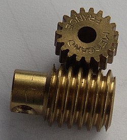
Worms resemble screws. A worm is meshed with a worm wheel, which looks similar to a spur gear.
Worm-and-gear sets are a simple and compact way to achieve a high torque, low speed gear ratio. For example, helical gears are normally limited to gear ratios of less than 10:1 while worm-and-gear sets vary from 10:1 to 500:1.[45] A disadvantage is the potential for considerable sliding action, leading to low efficiency.[46]
A worm gear is a species of helical gear, but its helix angle is usually somewhat large (close to 90 degrees) and its body is usually fairly long in the axial direction. These attributes give it screw like qualities. The distinction between a worm and a helical gear is that at least one tooth persists for a full rotation around the helix. If this occurs, it is a 'worm'; if not, it is a 'helical gear'. A worm may have as few as one tooth. If that tooth persists for several turns around the helix, the worm appears, superficially, to have more than one tooth, but what one in fact sees is the same tooth reappearing at intervals along the length of the worm. The usual screw nomenclature applies: a one-toothed worm is called single thread or single start; a worm with more than one tooth is called multiple thread or multiple start. The helix angle of a worm is not usually specified. Instead, the lead angle, which is equal to 90 degrees minus the helix angle, is given.
In a worm-and-gear set, the worm can always drive the gear. However, if the gear attempts to drive the worm, it may or may not succeed. Particularly if the lead angle is small, the gear's teeth may simply lock against the worm's teeth, because the force component circumferential to the worm is not sufficient to overcome friction. In traditional music boxes, however, the gear drives the worm, which has a large helix angle. This mesh drives the speed-limiter vanes which are mounted on the worm shaft.
Worm-and-gear sets that do lock are called self locking, which can be used to advantage, as when it is desired to set the position of a mechanism by turning the worm and then have the mechanism hold that position. An example is the machine head found on some types of stringed instruments.
If the gear in a worm-and-gear set is an ordinary helical gear only a single point of contact is achieved.[37][47] If medium to high power transmission is desired, the tooth shape of the gear is modified to achieve more intimate contact by making both gears partially envelop each other. This is done by making both concave and joining them at a saddle point; this is called a cone-drive[48] or "Double enveloping".
Worm gears can be right or left-handed, following the long-established practice for screw threads.[34]
Tooth profile
Profile of a spur gear
Another criterion to classify gears is the tooth profile, the shape of the cross-section of a tooth face by an imaginary cut perpendicular to the pitch surface, such as the transverse, normal, or axial plane.
The tooth profile is crucial for the smoothness and uniformity of the movement of matching gears, as well as for the friction and wear.
Artisanal
Wooden cogs set in bevel mortise wheels driving a millstone. Note wooden spur gears in the background.
The teeth of antique or artisanal gears that were cut by hand from sheet material, like those in the Antikythera mechanism, generally had simple profiles, such as triangles. [49] The teeth of larger gears — such as used in windmills — were usually pegs with simple shapes like cylinders, parallelepipeds, or triangular prisms inserted into a smooth wooden or metal wheel; or were holes with equally simple shapes cut into such a wheel.
Because of their sub-optimal profile, the effective gear ratio of such artisanal matching gears was not constant, but fluctuated over each tooth cycle, resulting in vibrations, noise, and accelerated wear.
A cage gear, also called a lantern gear or lantern pinion, is one of those artisanal gears having cylindrical rods for teeth, parallel to the axle and arranged in a circle around it, much as the bars on a round bird cage or lantern. The assembly is held together by disks at each end, into which the tooth rods and axle are set. Cage gears are more efficient than solid pinions,[citation needed] and dirt can fall through the rods rather than becoming trapped and increasing wear. They can be constructed with very simple tools as the teeth are not formed by cutting or milling, but rather by drilling holes and inserting rods.
Sometimes used in clocks, a cage gear should always be driven by a gearwheel, not used as the driver. The cage gear was not initially favoured by conservative clock makers. It became popular in turret clocks where dirty working conditions were most commonplace. Domestic American clock movements often used them. [citation needed]
Mathematical
In most modern gears, the tooth profile is usually not straight or circular, but of special form designed to achieve a constant angular velocity ratio.
There is an infinite variety of tooth profiles that will achieve this goal. In fact, given a fairly arbitrary[clarification needed] tooth shape, it is possible to develop a tooth profile for the mating gear that will do it.
Parallel and crossed axes
However, two constant velocity tooth profiles are the most commonly used in modern times for gears with parallel or crossed axes, based on the cycloid and involute curves.
Cycloidal gears were more common until the late 1800s. Since then, the involute has largely superseded it, particularly in drive train applications. The cycloid is in some ways the more interesting and flexible shape; however the involute has two advantages: it is easier to manufacture, and it permits the center-to-center spacing of the gears to vary over some range without ruining the constancy of the velocity ratio. Cycloidal gears only work properly if the center spacing is exactly right. Cycloidal gears are still commonly used in mechanical clocks.
Skew axes
Spiral bevel gears
For non-parallel axes with non-straight tooth cuts, the best tooth profile is one of several spiral bevel gear shapes. These include Gleason types (circular arc with non-constant tooth depth), Oerlikon and Curvex types (circular arc with constant tooth depth), Klingelnberg Cyclo-Palloid (Epicycloid with constant tooth depth) or Klingelnberg Palloid.[40]
The tooth faces in these gear types are not involute cylinders or cones but patches of octoidal surfaces.[50] Manufacturing such tooth faces may require a 5-axis milling machine.
Spiral bevel gears have the same advantages and disadvantages relative to their straight-cut cousins as helical gears do to spur gears, such as lower noise and vibration.[40] Simplified calculated bevel gears on the basis of an equivalent cylindrical gear in normal section with an involute tooth form show a deviant tooth form with reduced tooth strength by 10-28% without offset and 45% with offset.[51]
A rack is a toothed bar or rod that can be thought of as a sector gear with an infinitely large radius of curvature. Torque can be converted to linear force by meshing a rack with a round gear called a pinion: the pinion turns, while the rack moves in a straight line. Such a mechanism is used in the steering of automobiles to convert the rotation of the steering wheel into the left-to-right motion of the tie rod(s) that are attached to the front wheels.
Racks also feature in the theory of gear geometry, where, for instance, the tooth shape of an interchangeable set of gears may be specified for the rack (infinite radius), and the tooth shapes for gears of particular actual radii are then derived from that. The rack and pinion gear type is also used in a rack railway.
Non-circular gears are designed for special purposes. While a regular gear is optimized to transmit torque to another engaged member with minimum noise and wear and maximum efficiency, a non-circular gear's main objective might be ratio variations, axle displacement oscillations and more. Common applications include textile machines, potentiometers and continuously variable transmissions.
Non-rigid gears
Most gears are ideally rigid bodies which transmit torque and movement through the lever principle and contact forces between the teeth. Namely, the torque applied to one gear causes it to rotate as rigid body, so that its teeth push against those of the matched gear, which in turn rotates as a rigid body transmitting the torque to its axle. Some specialized gear escape this pattern, however.
A harmonic gear or strain wave gear is a specialized gearing mechanism often used in industrial motion control, robotics and aerospace for its advantages over traditional gearing systems, including lack of backlash, compactness and high gear ratios.
Though the diagram does not demonstrate the correct configuration, it is a "timing gear," conventionally with far more teeth than a traditional gear to ensure a higher degree of precision.
In a magnetic gear pair there is no contact between the two members; the torque is instead transmitted through magnetic fields. The cogs of each gear are constant magnets with periodic alternation of opposite magnetic poles on mating surfaces. Gear components are mounted with a backlash capability similar to other mechanical gearings. Although they cannot exert as much force as a traditional gear due to limits on magnetic field strength, such gears work without touching and so are immune to wear, have very low noise, minimal power losses from friction and can slip without damage making them very reliable.[52] They can be used in configurations that are not possible for gears that must be physically touching and can operate with a non-metallic barrier completely separating the driving force from the load. The magnetic coupling can transmit force into a hermetically sealed enclosure without using a radial shaft seal, which may leak. Magnetic gears are also used in brushless motors along with electromagnets to make the motor spin.
How many teeth a gear has, an integer. In the case of worms, it is the number of thread starts that the worm has.
Gear, wheel
The larger of two interacting gears or a gear on its own.
Pinion
The smaller of two interacting gears.
Path of contact
Path followed by the point of contact between two meshing gear teeth.
Line of action, pressure line
Line along which the force between two meshing gear teeth is directed. It has the same direction as the force vector. In general, the line of action changes from moment to moment during the period of engagement of a pair of teeth. For involute gears, however, the tooth-to-tooth force is always directed along the same line—that is, the line of action is constant. This implies that for involute gears the path of contact is also a straight line, coincident with the line of action—as is indeed the case.
Axis
Axis of revolution of the gear; center line of the shaft.
Pitch point
Point where the line of action crosses a line joining the two gear axes.
Pitch circle, pitch line
Circle centered on and perpendicular to the axis, and passing through the pitch point. A predefined diametral position on the gear where the circular tooth thickness, pressure angle and helix angles are defined.
Pitch diameter, d
A predefined diametral position on the gear where the circular tooth thickness, pressure angle and helix angles are defined. The standard pitch diameter is a design dimension and cannot be measured, but is a location where other measurements are made. Its value is based on the number of teeth (N), the normal module (mn; or normal diametral pitch, Pd), and the helix angle ():
Since it is impractical to calculate circular pitch with irrational numbers, mechanical engineers usually use a scaling factor that replaces it with a regular value instead. This is known as the module or modulus of the wheel and is simply defined as:
where m is the module and p the circular pitch. The units of module are customarily millimeters; an English Module is sometimes used with the units of inches. When the diametral pitch, DP, is in English units,
in conventional metric units.
The distance between the two axis becomes:
where a is the axis distance, z1 and z2 are the number of cogs (teeth) for each of the two wheels (gears). These numbers (or at least one of them) is often chosen among primes to create an even contact between every cog of both wheels, and thereby avoid unnecessary wear and damage. An even uniform gear wear is achieved by ensuring the tooth counts of the two gears meshing together are relatively prime to each other; this occurs when the greatest common divisor (GCD) of each gear tooth count equals 1, e.g. GCD(16,25)=1; if a 1:1 gear ratio is desired a relatively prime gear may be inserted in between the two gears; this maintains the 1:1 ratio but reverses the gear direction; a second relatively prime gear could also be inserted to restore the original rotational direction while maintaining uniform wear with all 4 gears in this case. Mechanical engineers, at least in continental Europe, usually use the module instead of circular pitch. The module, just like the circular pitch, can be used for all types of cogs, not just evolvent based straight cogs.[54]
Operating pitch diameters
Diameters determined from the number of teeth and the center distance at which gears operate.[34] Example for pinion:
Pitch surface
In cylindrical gears, cylinder formed by projecting a pitch circle in the axial direction. More generally, the surface formed by the sum of all the pitch circles as one moves along the axis. For bevel gears it is a cone.
Angle of action
Angle with vertex at the gear center, one leg on the point where mating teeth first make contact, the other leg on the point where they disengage.
Arc of action
Segment of a pitch circle subtended by the angle of action.
The complement of the angle between the direction that the teeth exert force on each other, and the line joining the centers of the two gears. For involute gears, the teeth always exert force along the line of action, which, for involute gears, is a straight line; and thus, for involute gears, the pressure angle is constant.
Outside diameter, Do
Diameter of the gear, measured from the tops of the teeth.
Root diameter
Diameter of the gear, measured at the base of the tooth.
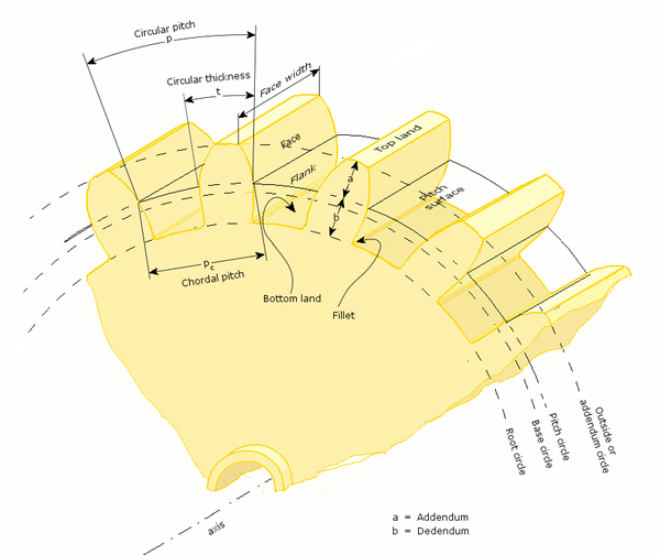
Addendum, a
Radial distance from the pitch surface to the outermost point of the tooth.
Dedendum, b
Radial distance from the depth of the tooth trough to the pitch surface.
Whole depth, ht
The distance from the top of the tooth to the root; it is equal to addendum plus dedendum or to working depth plus clearance.
Clearance
Distance between the root circle of a gear and the addendum circle of its mate.
Working depth
Depth of engagement of two gears, that is, the sum of their operating addendums.
Circular pitch, p
Distance from one face of a tooth to the corresponding face of an adjacent tooth on the same gear, measured along the pitch circle.
Diametral pitch, DP
Ratio of the number of teeth to the pitch diameter. Could be measured in teeth per inch or teeth per centimeter, but conventionally has units of per inch of diameter. Where the module, m, is in metric units
in imperial units
Base circle
In involute gears, the tooth profile is generated by the involute of the base circle. The radius of the base circle is somewhat smaller than that of the pitch circle
Base pitch, normal pitch, pb
In involute gears, distance from one face of a tooth to the corresponding face of an adjacent tooth on the same gear, measured along the base circle
Interference
Contact between teeth other than at the intended parts of their surfaces
Interchangeable set
A set of gears, any of which mates properly with any other
Helical gear
Helix angle, ψ
the Angle between a tangent to the helix and the gear axis. It is zero in the limiting case of a spur gear, albeit it can be considered as the hypotenuse angle as well.
Normal circular pitch, pn
Circular pitch in the plane normal to the teeth.
Transverse circular pitch, p
Circular pitch in the plane of rotation of the gear. Sometimes just called "circular pitch".
Several other helix parameters can be viewed either in the normal or transverse planes. The subscript n usually indicates the normal.
Worm gear
Lead
Distance from any point on a thread to the corresponding point on the next turn of the same thread, measured parallel to the axis.
Linear pitch, p
Distance from any point on a thread to the corresponding point on the adjacent thread, measured parallel to the axis. For a single-thread worm, lead and linear pitch are the same.
Lead angle, λ
Angle between a tangent to the helix and a plane perpendicular to the axis. Note that the complement of the helix angle is usually given for helical gears.
Pitch diameter, dw
Same as described earlier in this list. Note that for a worm it is still measured in a plane perpendicular to the gear axis, not a tilted plane.
Subscript w denotes the worm, subscript g denotes the gear.
Tooth contact
Line of contact
Path of action
Line of action
Plane of action
Lines of contact (helical gear)
Arc of action
Length of action
Limit diameter
Face advance
Zone of action
Point of contact
Any point at which two tooth profiles touch each other.
Line of contact
A line or curve along which two tooth surfaces are tangent to each other.
Path of action
The locus of successive contact points between a pair of gear teeth, during the phase of engagement. For conjugate gear teeth, the path of action passes through the pitch point. It is the trace of the surface of action in the plane of rotation.
Line of action
The path of action for involute gears. It is the straight line passing through the pitch point and tangent to both base circles.
Surface of action
The imaginary surface in which contact occurs between two engaging tooth surfaces. It is the summation of the paths of action in all sections of the engaging teeth.
Plane of action
The surface of action for involute, parallel axis gears with either spur or helical teeth. It is tangent to the base cylinders.
Zone of action (contact zone)
For involute, parallel-axis gears with either spur or helical teeth, is the rectangular area in the plane of action bounded by the length of action and the effective face width.
Path of contact
The curve on either tooth surface along which theoretical single point contact occurs during the engagement of gears with crowned tooth surfaces or gears that normally engage with only single point contact.
Length of action
The distance on the line of action through which the point of contact moves during the action of the tooth profile.
Arc of action, Qt
The arc of the pitch circle through which a tooth profile moves from the beginning to the end of contact with a mating profile.
Arc of approach, Qa
The arc of the pitch circle through which a tooth profile moves from its beginning of contact until the point of contact arrives at the pitch point.
Arc of recess, Qr
The arc of the pitch circle through which a tooth profile moves from contact at the pitch point until contact ends.
Contact ratio, mc or ε
The number of angular pitches through which a tooth surface rotates from the beginning to the end of contact. In a simple way, it can be defined as a measure of the average number of teeth in contact during the period during which a tooth comes and goes out of contact with the mating gear.
Transverse contact ratio, mp or εα
The contact ratio in a transverse plane. It is the ratio of the angle of action to the angular pitch. For involute gears it is most directly obtained as the ratio of the length of action to the base pitch.
Face contact ratio, mF or εβ
The contact ratio in an axial plane, or the ratio of the face width to the axial pitch. For bevel and hypoid gears it is the ratio of face advance to circular pitch.
Total contact ratio, mt or εγ
The sum of the transverse contact ratio and the face contact ratio.
Modified contact ratio, mo
For bevel gears, the square root of the sum of the squares of the transverse and face contact ratios.
Limit diameter
Diameter on a gear at which the line of action intersects the maximum (or minimum for internal pinion) addendum circle of the mating gear. This is also referred to as the start of active profile, the start of contact, the end of contact, or the end of active profile.
Start of active profile (SAP)
Intersection of the limit diameter and the involute profile.
Face advance
Distance on a pitch circle through which a helical or spiral tooth moves from the position at which contact begins at one end of the tooth trace on the pitch surface to the position where contact ceases at the other end.
Tooth thickness
Tooth thickness
Thickness relationships
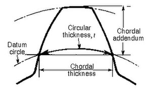
Chordal thickness
Tooth thickness measurement over pins
Span measurement
Long and short addendum teeth
Circular thickness
Length of arc between the two sides of a gear tooth, on the specified datum circle.
Transverse circular thickness
Circular thickness in the transverse plane.
Normal circular thickness
Circular thickness in the normal plane. In a helical gear it may be considered as the length of arc along a normal helix.
Axial thickness
In helical gears and worms, tooth thickness in an axial cross section at the standard pitch diameter.
Base circular thickness
In involute teeth, length of arc on the base circle between the two involute curves forming the profile of a tooth.
Normal chordal thickness
Length of the chord that subtends a circular thickness arc in the plane normal to the pitch helix. Any convenient measuring diameter may be selected, not necessarily the standard pitch diameter.
Chordal addendum (chordal height)
Height from the top of the tooth to the chord subtending the circular thickness arc. Any convenient measuring diameter may be selected, not necessarily the standard pitch diameter.
Profile shift
Displacement of the basic rack datum line from the reference cylinder, made non-dimensional by dividing by the normal module. It is used to specify the tooth thickness, often for zero backlash.
Rack shift
Displacement of the tool datum line from the reference cylinder, made non-dimensional by dividing by the normal module. It is used to specify the tooth thickness.
Measurement over pins
Measurement of the distance taken over a pin positioned in a tooth space and a reference surface. The reference surface may be the reference axis of the gear, a datum surface or either one or two pins positioned in the tooth space or spaces opposite the first. This measurement is used to determine tooth thickness.
Span measurement
Measurement of the distance across several teeth in a normal plane. As long as the measuring device has parallel measuring surfaces that contact on an unmodified portion of the involute, the measurement wis along a line tangent to the base cylinder. It is used to determine tooth thickness.
Modified addendum teeth
Teeth of engaging gears, one or both of which have non-standard addendum.
Full-depth teeth
Teeth in which the working depth equals 2.000 divided by the normal diametral pitch.
Stub teeth
Teeth in which the working depth is less than 2.000 divided by the normal diametral pitch.
Equal addendum teeth
Teeth in which two engaging gears have equal addendums.
Long and short-addendum teeth
Teeth in which the addendums of two engaging gears are unequal.
Undercut
Undercut
An undercut is a condition in generated gear teeth when any part of the fillet curve lies inside of a line drawn tangent to the working profile at its point of juncture with the fillet. Undercut may be deliberately introduced to facilitate finishing operations. With undercut the fillet curve intersects the working profile. Without undercut the fillet curve and the working profile have a common tangent.
Root fillet
or fillet curve, the concave portion of the tooth profile where it joins the bottom of the tooth space.2
Pitch
Pitch is the distance between a point on one tooth and the corresponding point on an adjacent tooth.[34] It is a dimension measured along a line or curve in the transverse, normal, or axial directions. The use of the single word pitch without qualification may be ambiguous, and for this reason it is preferable to use specific designations such as transverse circular pitch, normal base pitch, axial pitch.
Pitch
Tooth pitch
Base pitch relationships
Principal pitches
Circular pitch, p
Arc distance along a specified pitch circle or pitch line between corresponding profiles of adjacent teeth.
Transverse circular pitch, pt
Circular pitch in the transverse plane.
Normal circular pitch, pn, pe
Circular pitch in the normal plane, and also the length of the arc along the normal pitch helix between helical teeth or threads.
Axial pitch, px
Linear pitch in an axial plane and in a pitch surface. In helical gears and worms, axial pitch has the same value at all diameters. In gearing of other types, axial pitch may be confined to the pitch surface and may be a circular measurement. The term axial pitch is preferred to the term linear pitch. The axial pitch of a helical worm and the circular pitch of its worm gear are the same.
Normal base pitch, pN, pbn
An involute helical gear is the base pitch in the normal plane. It is the normal distance between parallel helical involute surfaces on the plane of action in the normal plane, or is the length of arc on the normal base helix. It is a constant distance in any helical involute gear.
Transverse base pitch, pb, pbt
In an involute gear, the pitch is on the base circle or along the line of action. Corresponding sides of involute gear teeth are parallel curves, and the base pitch is the constant and fundamental distance between them along a common normal in a transverse plane.
Diametral pitch (transverse), Pd
Ratio of the number of teeth to the standard pitch diameter in inches.
Normal diametral pitch, Pnd
Value of diametral pitch in a normal plane of a helical gear or worm.
Angular pitch, θN, τ
Angle subtended by the circular pitch, usually expressed in radians.
Backlash is the error in motion that occurs when gears change direction. It exists because there is always some gap between the trailing face of the driving tooth and the leading face of the tooth behind it on the driven gear, and that gap must be closed before force can be transferred in the new direction. The term "backlash" can also be used to refer to the size of the gap, not just the phenomenon it causes; thus, one could speak of a pair of gears as having, for example, "0.1 mm of backlash." A pair of gears could be designed to have zero backlash, but this would presuppose perfection in manufacturing, uniform thermal expansion characteristics throughout the system, and no lubricant. Therefore, gear pairs are designed to have some backlash. It is usually provided by reducing the tooth thickness of each gear by half the desired gap distance. In the case of a large gear and a small pinion, however, the backlash is usually taken entirely off the gear and the pinion is given full sized teeth. Backlash can also be provided by moving the gears further apart. The backlash of a gear train equals the sum of the backlash of each pair of gears, so in long trains backlash can become a problem.
For situations that require precision, such as instrumentation and control, backlash can be minimized through one of several techniques. For instance, the gear can be split along a plane perpendicular to the axis, one half fixed to the shaft in the usual manner, the other half placed alongside it, free to rotate about the shaft, but with springs between the two-halves providing relative torque between them, so that one achieves, in effect, a single gear with expanding teeth. Another method involves tapering the teeth in the axial direction and letting the gear slide in the axial direction to take up slack.
Standard pitches and the module system
Although gears can be made with any pitch, for convenience and interchangeability standard pitches are frequently used. Pitch is a property associated with linear dimensions and so differs whether the standard values are in the imperial (inch) or metric systems. Using inch measurements, standard diametral pitch values with units of "per inch" are chosen; the diametral pitch is the number of teeth on a gear of one inch pitch diameter. Common standard values for spur gears are 3, 4, 5, 6, 8, 10, 12, 16, 20, 24, 32, 48, 64, 72, 80, 96, 100, 120, and 200.[55] Certain standard pitches such as 1⁄10 and 1⁄20 in inch measurements, which mesh with linear rack, are actually (linear) circular pitch values with units of "inches"[55]
When gear dimensions are in the metric system the pitch specification is generally in terms of module or modulus, which is effectively a length measurement across the pitch diameter. The term module is understood to mean the pitch diameter in millimetres divided by the number of teeth. When the module is based upon inch measurements, it is known as the English module to avoid confusion with the metric module. Module is a direct dimension ("millimeters per tooth"), unlike diametral pitch, which is an inverse dimension ("teeth per inch"). Thus, if the pitch diameter of a gear is 40mm and the number of teeth 20, the module is 2, which means that there are 2mm of pitch diameter for each tooth.[56] The preferred standard module values are 0.1, 0.2, 0.3, 0.4, 0.5, 0.6, 0.8, 1.0, 1.25, 1.5, 2.0, 2.5, 3, 4, 5, 6, 8, 10, 12, 16, 20, 25, 32, 40 and 50.[57]
Gears present several failure mechanisms that can happen at the same time according to the rotational speed and the load applied. These mechanisms are: wear, scuffing, pitting, micro-pitting, tooth flank fracture and tooth root fatigue fracture.
These mechanisms are due to several phenomena: friction, contact (Hertzian pressure, sliding/rolling), bending fatigue and lack of lubrication. All these phenomena can happen simultaneously and they lead to the failure of the gearbox.
The standard ISO 6336[58] and AGMA 2001[59] provide information regarding these failure mechanisms and define calculation methods to verify if a gear is safe from such phenomena. Even if the standards provide this information they strongly suggest the need to perform experimental tests because the standards cannot cover all the possible combinations of geometry, material, heat treatment, ecc.
There are different tests to study the behaviour of the gear. Due to the fact that the failure mechanisms can happen simultaneously the tested gears are designed in order to isolate only one failure mechanism.[60][61]
Gear model in modern physics
Modern physics adopted the gear model in different ways. In the nineteenth century, James Clerk Maxwell developed a model of electromagnetism in which magnetic field lines were rotating tubes of incompressible fluid. Maxwell used a gear wheel and called it an "idle wheel" to explain the electric current as a rotation of particles in opposite directions to that of the rotating field lines.[62]
More recently, quantum physics uses "quantum gears" in their model. A group of gears can serve as a model for several different systems, such as an artificially constructed nanomechanical device or a group of ring molecules.[63]
The gear mechanism was previously considered exclusively artificial, but as early as 1957, gears had been recognized in the hind legs of various species of planthoppers[65] and scientists from the University of Cambridge characterized their functional significance in 2013 by doing high-speed photography of the nymphs of Issus coleoptratus at Cambridge University.[66][67] These gears are found only in the nymph forms of all planthoppers, and are lost during the final molt to the adult stage.[68] In I. coleoptratus, each leg has a 400-micrometer strip of teeth, pitch radius 200 micrometers, with 10 to 12 fully interlocking spur-type gear teeth, including filleted curves at the base of each tooth to reduce the risk of shearing.[69] The joint rotates like mechanical gears, and synchronizes Issus's hind legs when it jumps to within 30 microseconds, preventing yaw rotation.[70][71][66] The gears are not connected all the time. One is located on each of the juvenile insect's hind legs, and when it prepares to jump, the two sets of teeth lock together. As a result, the legs move in almost perfect unison, giving the insect more power as the gears rotate to their stopping point and then unlock.[70]
1 2 3 4 5 American Gear Manufacturers Association; American National Standards Institute, Gear Nomenclature, Definitions of Terms with Symbols (ANSI/AGMA 1012-G05ed.), American Gear Manufacturers Association
↑ Canfield, Stephen (1997), "Gear Types", Dynamics of Machinery, Tennessee Tech University, Department of Mechanical Engineering, ME 362 lecture notes, archived from the original on 29 August 2008.
↑ Kravchenko A.I., Bovda A.M. Gear with magnetic couple. Pat. of Ukraine N. 56700 – Bul. N. 2, 2011 – F16H 49/00.
↑ ISO/DIS 21771:2007: "Gears – Cylindrical Involute Gears and Gear Pairs – Concepts and Geometry", International Organization for Standardization, (2007)
↑ Gunnar Dahlvig (1982), "Construction elements and machine construction", Konstruktionselement och maskinbyggnad (in Swedish), 7, ISBN978-9140115546
↑ Siegel, Daniel M. (1991). Innovation in Maxwell's Electromagnetic Theory: Molecular Vortices, Displacement Current, and Light. University of Chicago Press. ISBN978-0521353656.
↑ Sander, K. (1957), "Bau und Funktion des Sprungapparates von Pyrilla perpusilla WALKER (Homoptera - Fulgoridae)", Zool. Jb. Jena (Anat.) (in German), 75: 383–388
Buckingham, Earle (1949), Analytical Mechanics of Gears, McGraw-Hill Book Co..
Coy, John J.; Townsend, Dennis P.; Zaretsky, Erwin V. (1985), Gearing(PDF), NASA Scientific and Technical Information Branch, NASA-RP-1152; AVSCOM Technical Report 84-C-15.
Kravchenko A.I., Bovda A.M. Gear with magnetic couple. Pat. of Ukraine N. 56700 – Bul. N. 2, 2011 – F16H 49/00.
Sclater, Neil. (2011). "Gears: devices, drives and mechanisms." Mechanisms and Mechanical Devices Sourcebook. 5th ed. New York: McGraw Hill. pp.131–174. ISBN9780071704427. Drawings and designs of various gearings.
This page is based on this Wikipedia article Text is available under the CC BY-SA 4.0 license; additional terms may apply. Images, videos and audio are available under their respective licenses.