Bevel gear

Last updated

Bevel gears are gears where the axes of the two shafts intersect and the tooth-bearing faces of the gears themselves are conically shaped. Bevel gears are most often mounted on shafts that are 90 degrees apart, but can be designed to work at other angles as well. [1] The pitch surface of bevel gears is a cone, known as a pitch cone. Bevel gears change the axis of rotation of rotational power delivery and are widely used in mechanical settings.
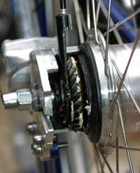
Contents

Bevel gear on roller shutter door. Crown gears on roller-door at Ngcobo.jpg
Bevel gear on roller shutter door.
Regardless of the operating angle, the gear axes must intersect (at a point O) Beve gear schematic.png
Regardless of the operating angle, the gear axes must intersect (at a point O)
Bevel gear lifts floodgate by means of central screw. Bevel gear.jpg
Bevel gear lifts floodgate by means of central screw.
Bevel ring gear on the rear wheel of a shaft-driven bicycle Bevelgear.jpg
Bevel ring gear on the rear wheel of a shaft-driven bicycle
Spiral bevel gear Gear-kegelzahnrad.svg
Spiral bevel gear

Introduction

Two important concepts in gearing are pitch surface and pitch angle. The pitch surface of a gear is the imaginary toothless surface that you would have by averaging out the peaks and valleys of the individual teeth. The pitch surface of an ordinary gear is the shape of a cylinder. The pitch angle of a gear is the angle between the face of the pitch surface and the axis.

The most familiar kinds of bevel gears have pitch angles of less than 90 degrees and therefore are cone-shaped. This type of bevel gear is called external because the gear teeth point outward. The pitch surfaces of meshed external bevel gears are coaxial with the gear shafts; the apexes of the two surfaces are at the point of intersection of the shaft axes.

The use of a genuine bevel gear has even greater importance for the reliability of the axle than any other spare part. Bevel gears that have pitch angles of greater than ninety degrees have teeth that point inward and are called internal bevel gears.

Bevel gears that have pitch angles of exactly 90 degrees have teeth that point outward parallel with the axis and resemble the points on a crown, whence the name crown gear.

Hypoid bevel gear Bogenverzahnung.JPG
Hypoid bevel gear

Mitre gears

Miter gears AKegelraeder.jpg
Miter gears

Mitre gears are a special case of bevel gears that have equal numbers of teeth. The shafts are positioned at right angles from each other, and the gears have matching pitch surfaces and angles, with a conically-shaped pitch surface. [2]

Mitre gears are useful for transmitting rotational motion at a 90-degree angle with a 1:1 ratio.

Geometry of a bevel gear

A double-helical bevel gear made by Citroen in 1927 for the Mirejovice water power plant Double-helical bevel gear Citroen.jpg
A double-helical bevel gear made by Citroën in 1927 for the Miřejovice water power plant

The cylindrical gear tooth profile corresponds to an involute (i.e. a triangle wave projected on the circumference of a circle), whereas the bevel gear tooth profile is an octoid[ definition needed ] (i.e. a triangle wave projected on the normal path of a circle of a sphere). All traditional bevel gear generators (such as Gleason, Klingelnberg, Heidenreich & Harbeck, WMW Modul) manufacture bevel gears with an octoidal tooth profile. IMPORTANT: For 5-axis milled bevel gear sets it is important to choose the same calculation / layout like the conventional manufacturing method. Simplified calculated bevel gears on the basis of an equivalent cylindrical gear in normal section with an involute tooth form show a deviant tooth form with reduced tooth strength by 10-28% without offset and 45% with offset [Diss. Hünecke, TU Dresden]. Furthermore, those "involute bevel gear sets" cause more noise.

Teeth

There are two issues regarding tooth shape. One is the cross-sectional profile of the individual tooth. The other is the line or curve on which the tooth is set on the face of the gear: in other words the line or curve along which the cross-sectional profile is projected to form the actual three-dimensional shape of the tooth. The primary effect of both the cross-sectional profile and the tooth line or curve is on the smoothness of operation of the gears. Some result in a smoother gear action than others.

Tooth line

The teeth on bevel gears can be straight, spiral or "zerol".

Straight tooth lines

In straight bevel gears, the teeth are straight and parallel to the generators of the cone. This is the simplest form of bevel gear. It resembles a spur gear, only conical rather than cylindrical. The gears in the floodgate picture are straight bevel gears. In straight bevel gear sets, when each tooth engages, it impacts the corresponding tooth and simply curving the gear teeth can solve the problem.

Spiral tooth lines

Spiral bevel gears have their teeth formed along spiral lines. They are somewhat analogous to cylindrical type helical gears in that the teeth are angled; however, with spiral gears, the teeth are also curved.

The advantage of the spiral tooth over the straight tooth is that they engage more gradually. The contact between the teeth starts at one end of the gear and then spreads across the whole tooth. This results in a less abrupt transfer of force when a new pair of teeth come into play. With straight bevel gears, the abrupt tooth engagement causes noise, especially at high speeds, and impact stress on the teeth which makes them unable to take heavy loads at high speeds without breaking. For these reasons, straight bevel gears are generally limited to use at linear speeds less than 1000 feet/min; or, for small gears, under 1000 rpm. [3]

Zerol tooth lines

Zerol bevel gears are an intermediate type between straight and spiral bevel gears. Their teeth are curved, but not angled. Zerol bevel gears are designed with the intent of duplicating the characteristics of a straight bevel gear, but they are produced using a spiral bevel cutting process.

Manufacturing bevel gears

Materials used in gear manufacturing process

Bevel gearing Engrenage conique concourant 14dts mod5.svg
Bevel gearing

Applications

The bevel gear has many diverse applications such as locomotives, marine applications, automobiles, printing presses, cooling towers, power plants, steel plants, railway track inspection machines, etc.

For examples, see the following articles on:

Bevel gears on grain mill at Dordrecht. Note wooden teeth inserts on one of the gears. Bevel gears on grain mill at Dordrecht, Eastern Cape.jpg
Bevel gears on grain mill at Dordrecht. Note wooden teeth inserts on one of the gears.

Advantages

Disadvantages

See also

Related Research Articles

<span class="mw-page-title-main">Cam (mechanism)</span> Rotating or sliding component that transmits variable motion to a follower

A cam is a rotating or sliding piece in a mechanical linkage used especially in transforming rotary motion into linear motion. It is often a part of a rotating wheel or shaft that strikes a lever at one or more points on its circular path. The cam can be a simple tooth, as is used to deliver pulses of power to a steam hammer, for example, or an eccentric disc or other shape that produces a smooth reciprocating motion in the follower, which is a lever making contact with the cam. A cam timer is similar, and were widely used for electric machine control before the advent of inexpensive electronics, microcontrollers, integrated circuits, programmable logic controllers and digital control.

<span class="mw-page-title-main">Logarithmic spiral</span> Self-similar growth curve

A logarithmic spiral, equiangular spiral, or growth spiral is a self-similar spiral curve that often appears in nature. The first to describe a logarithmic spiral was Albrecht Dürer (1525) who called it an "eternal line". More than a century later, the curve was discussed by Descartes (1638), and later extensively investigated by Jacob Bernoulli, who called it Spira mirabilis, "the marvelous spiral".

<span class="mw-page-title-main">Gear</span> Rotating circular machine part with teeth that mesh with another toothed part

A gear is a rotating circular machine part having cut teeth or, in the case of a cogwheel or gearwheel, inserted teeth, which mesh with another (compatible) toothed part to transmit rotational power. While doing so, they can change the torque and rotational speed being transmitted and also change the rotational axis of the power being transmitted. The teeth on the two meshing gears all have the same shape.

<span class="mw-page-title-main">Differential (mechanical device)</span> Type of simple planetary gear train

A differential is a gear train with three drive shafts that has the property that the rotational speed of one shaft is the average of the speeds of the others. A common use of differentials is in motor vehicles, to allow the wheels at each end of a drive axle to rotate at different speeds while cornering. Other uses include clocks and analog computers.

<span class="mw-page-title-main">Rack and pinion</span> Type of linear actuator

A rack and pinion is a type of linear actuator that comprises a circular gear engaging a linear gear. Together, they convert between rotational motion and linear motion. Rotating the pinion causes the rack to be driven in a line. Conversely, moving the rack linearly will cause the pinion to rotate. A rack-and-pinion drive can use both straight and helical gears. Though some suggest helical gears are quieter in operation, no hard evidence supports this theory. Helical racks, while being more affordable, have proven to increase side torque on the datums, increasing operating temperature leading to premature wear. Straight racks require a lower driving force and offer increased torque and speed per fraction of gear ratio which allows lower operating temperature and lessens viscal friction and energy use. The maximum force that can be transmitted in a rack-and-pinion mechanism is determined by the torque on the pinion and its size, or, conversely, by the force on the rack and the size of the pinion.

<span class="mw-page-title-main">Involute gear</span> Gear with teeth whose profile is an involute of a circle

The involute gear profile is the most commonly used system for gearing today, with cycloid gearing still used for some specialties such as clocks. In an involute gear, the profiles of the teeth are involutes of a circle. The involute of a circle is the spiraling curve traced by the end of an imaginary taut string unwinding itself from that stationary circle called the base circle, or (equivalently) a triangle wave projected on the circumference of a circle.

<span class="mw-page-title-main">Hobbing</span> Process used to cut teeth into gears

Hobbing is a machining process for gear cutting, cutting splines, and cutting sprockets using a hobbing machine, a specialized milling machine. The teeth or splines of the gear are progressively cut into the material by a series of cuts made by a cutting tool called a hob.

<span class="mw-page-title-main">Turning</span> Machining process

Turning is a machining process in which a cutting tool, typically a non-rotary tool bit, describes a helix toolpath by moving more or less linearly while the workpiece rotates.

<span class="mw-page-title-main">Gear train</span> Mechanical transmission using multiple gears

A gear train or gear set is a machine element of a mechanical system formed by mounting two or more gears on a frame such that the teeth of the gears engage.

<span class="mw-page-title-main">Worm drive</span> Gear arrangement


A worm drive is a gear arrangement in which a worm meshes with a worm wheel. The two elements are also called the worm screw and worm gear. The terminology is often confused by imprecise use of the term worm gear to refer to the worm, the worm wheel, or the worm drive as a unit.

<span class="mw-page-title-main">Cycloid gear</span>

A cycloidal gear is a toothed gear with a cycloidal profile. Such gears are used in mechanical clocks and watches, rather than the involute gear form used for most other gears. Cycloidal gears have advantages over involute gears in such applications in being able to be produced flat, and having fewer points of contact.

<span class="mw-page-title-main">Dental instrument</span> Tools of the dental profession

Dental instruments are tools that dental professionals use to provide dental treatment. They include tools to examine, manipulate, treat, restore, and remove teeth and surrounding oral structures.

<span class="mw-page-title-main">Spur gear</span> Simplest type of gear

Spur gears or straight-cut gears are the simplest type of gear. They consist of a cylinder or disk with teeth projecting radially. Viewing the gear at 90 degrees from the shaft length the tooth faces are straight and aligned parallel to the axis of rotation. Looking down the length of the shaft, a tooth's cross section is usually not triangular. Instead of being straight the sides of the cross section have a curved form to achieve a constant drive ratio. Spur gears mesh together correctly only if fitted to parallel shafts. No axial thrust is created by the tooth loads. Spur gears are excellent at moderate speeds but tend to be noisy at high speeds.

<span class="mw-page-title-main">Hirth joint</span> Type of mechanical connection

A Hirth joint or Hirth coupling is a type of mechanical connection named after its developer Albert Hirth. It is used to connect two pieces of a shaft together and is characterized by tapered teeth that mesh together on the end faces of each half shaft.

<span class="mw-page-title-main">Profile angle</span>

The profile angle of a gear is the angle at a specified pitch point between a line tangent to a tooth surface and the line normal to the pitch surface. This definition is applicable to every type of gear for which a pitch surface can be defined. The profile angle gives the direction of the tangent to a tooth profile.

<span class="mw-page-title-main">Spiral bevel gear</span>

A spiral bevel gear is a bevel gear with helical teeth. The main application of this is in a vehicle differential, where the direction of drive from the drive shaft must be turned 90 degrees to drive the wheels. The helical design produces less vibration and noise than conventional straight-cut or spur-cut gear with straight teeth.

A spline is a ridge or tooth on a drive shaft that matches with a groove in a mating piece and transfers torque to it, maintaining the angular correspondence between them.

<span class="mw-page-title-main">Mechanism (engineering)</span> Device used to transfer forces via non-electric means

In engineering, a mechanism is a device that transforms input forces and movement into a desired set of output forces and movement. Mechanisms generally consist of moving components which may include:

Hypoid gearboxes are gearboxes having axes that are non-intersecting and not parallel. The hypoid gearboxes are a subcategory of spiral bevel gearbox with the axes of gears at an offset from one another. In comparison to the conical geometry of a spiral bevel gear, the basic geometry of hypoid gear is hyperbolic. The spiral angle of the pinion is larger than the spiral angle of the gear in a hypoid gearbox, so the pinion diameter can be larger than that of a bevel gear pinion. This helps in attaining an enhanced contact surface and a better tooth strength which allows for higher gear ratios and scope of higher torque transmission. Bearings can also be used on both sides of gears for extra rigidity as the offset between the axes allows the scope for extra support.

References

  1. Fred Herbert Colvin; Frank Arthur Stanley (1914). American Machinists' Handbook and Dictionary of Shop Terms: A Reference Book of math Shop and Drawing Room Data, Methods and Definitions. McGraw-Hill book Company, Incorporated. p. 121. Retrieved 14 August 2014.
  2. "What is the definition of miter gear?". toolingu.com. Retrieved 2014-03-11.
  3. Doughty and Vallance, Design of Machine Members.

How Bevel Gears Work on YouTube