Method of connecting two rotating shafts or pulleys
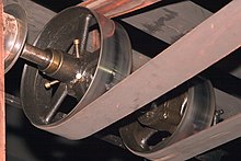
Flat beltFlat belt drive in the machine shop at the Hagley Museum
A belt is a loop of flexible material used to link two or more rotating shafts mechanically, most often parallel. Belts may be used as a source of motion, to transmit power efficiently or to track relative movement. Belts are looped over pulleys and may have a twist between the pulleys, and the shafts need not be parallel.
In a two pulley system, the belt can either drive the pulleys normally in one direction (the same if on parallel shafts), or the belt may be crossed, so that the direction of the driven shaft is reversed (the opposite direction to the driver if on parallel shafts). The belt drive can also be used to change the speed of rotation, either up or down, by using different sized pulleys.
As a source of motion, a conveyor belt is one application where the belt is adapted to carry a load continuously between two points.
History
The mechanical belt drive, using a pulley machine, was first mentioned in the text of the Dictionary of Local Expressions by the Han Dynasty philosopher, poet, and politician Yang Xiong (53–18 BC) in 15 BC, used for a quilling machine that wound silk fibres onto bobbins for weavers' shuttles.[1] The belt drive is an essential component of the invention of the spinning wheel.[2][3] The belt drive was not only used in textile technologies, it was also applied to hydraulic-powered bellows dated from the 1st century AD.[2]
Power transmission
Belts are the cheapest utility for power transmission between shafts that may not be axially aligned. Power transmission is achieved by purposely designed belts and pulleys. The variety of power transmission needs that can be met by a belt-drive transmission system are numerous, and this has led to many variations on the theme. Belt drives run smoothly and with little noise, and provide shock absorption for motors, loads, and bearings when the force and power needed changes. A drawback to belt drives is that they transmit less power than gears or chain drives. However, improvements in belt engineering allow use of belts in systems that formerly only allowed chain drives or gears.
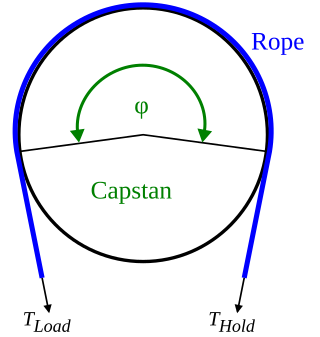
Power transmitted between a belt and a pulley is expressed as the product of difference of tension and belt velocity:
where and are tensions in the tight side and slack side of the belt respectively. They are related as
where is the coefficient of friction, and is the angle (in radians) subtended by contact surface at the centre of the pulley.
Belt drives are simple, inexpensive, and do not require axially aligned shafts. They help protect machinery from overload and jam, and damp and isolate noise and vibration. Load fluctuations are shock-absorbed (cushioned). They need no lubrication and minimal maintenance. They have high efficiency (90–98%, usually 95%), high tolerance for misalignment, and are of relatively low cost if the shafts are far apart. Clutch action can be achieved by shifting the belt to a free turning pulley or by releasing belt tension. Different speeds can be obtained by stepped or tapered pulleys.
The angular-velocity ratio may not be exactly constant or equal to that of the pulley diameters, due to slip and stretch. However, this problem can be largely solved by the use of toothed belts. Working temperatures range from −35 to 85°C (−31 to 185°F). Adjustment of centre distance or addition of an idler pulley is crucial to compensate for wear and stretch.
Flat belts
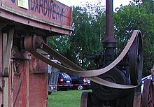
The drive belt: used to transfer power from the engine's flywheel. Here shown driving a threshing machine.A small section of a wide flat belt made of layers of leather with the fastener on one end, shown in an exhibit at the Suffolk Mills in Lowell, MassachusettsFlat belt connectorsFlat belt connecting tool
Flat belts were widely used in the 19th and early 20th centuries in line shafting to transmit power in factories.[4] They were also used in countless farming, mining, and logging applications, such as bucksaws, sawmills, threshers, silo blowers, conveyors for filling corn cribs or haylofts, balers, water pumps (for wells, mines, or swampy farm fields), and electrical generators. Flat belts are still used today, although not nearly as much as in the line-shaft era. The flat belt is a simple system of power transmission that was well suited for its day. It can deliver high power at high speeds(373kW at 51m/s; 115mph), in cases of wide belts and large pulleys. Wide-belt-large-pulley drives are bulky, consuming much space while requiring high tension, leading to high loads, and are poorly suited to close-centers applications. V-belts have mainly replaced flat belts for short-distance power transmission; and longer-distance power transmission is typically no longer done with belts at all. For example, factory machines now tend to have individual electric motors.
Because flat belts tend to climb towards the higher side of the pulley, pulleys were made with a slightly convex or "crowned" surface (rather than flat) to allow the belt to self-center as it runs. Flat belts also tend to slip on the pulley face when heavy loads are applied, and many proprietary belt dressings were available that could be applied to the belts to increase friction, and so power transmission.
Flat belts were traditionally made of leather or fabric. Early flour mills in Ukraine had leather belt drives. After World War I, there was such a shortage of shoe leather that people cut up the belt drives to make shoes. Selling shoes was more profitable than selling flour for a time.[when?] Flour milling soon came to a standstill and bread prices rose, contributing to famine conditions.[5] Leather drive belts were put to another use during the Rhodesian Bush War (1964–1979): To protect riders of cars and busses from land mines, layers of leather belt drives were placed on the floors of vehicles in danger zones. Today most belt drives are made of rubber or synthetic polymers. Grip of leather belts is often better if they are assembled with the hair side (outer side) of the leather against the pulley, although some belts are instead given a half-twist before joining the ends (forming a Möbius strip), so that wear can be evenly distributed on both sides of the belt. Belts ends are joined by lacing the ends together with leather thonging (the oldest of the methods),[6][7] steel comb fasteners and/or lacing,[8] or by gluing or welding (in the case of polyurethane or polyester). Flat belts were traditionally jointed, and still usually are, but they can also be made with endless construction.
Rope drives
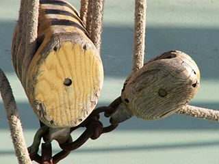
In the mid 19th century, British millwrights discovered that multi-grooved pulleys connected by ropes outperformed flat pulleys connected by leather belts. Wire ropes were occasionally used, but cotton, hemp, manila hemp and flax rope saw the widest use. Typically, the rope connecting two pulleys with multiple V-grooves was spliced into a single loop that traveled along a helical path before being returned to its starting position by an idler pulley that also served to maintain the tension on the rope. Sometimes, a single rope was used to transfer power from one multiple-groove drive pulley to several single- or multiple-groove driven pulleys in this way.
In general, as with flat belts, rope drives were used for connections from stationary engines to the jack shafts and line shafts of mills, and sometimes from line shafts to driven machinery. Unlike leather belts, however, rope drives were sometimes used to transmit power over relatively long distances. Over long distances, intermediate sheaves were used to support the "flying rope", and in the late 19th century, this was considered quite efficient.[9][10][11]
Round belts
Round belts are a circular cross section belt designed to run in a pulley with a 60 degree V-groove. Round grooves are only suitable for idler pulleys that guide the belt, or when (soft) O-ring type belts are used. The V-groove transmits torque through a wedging action, thus increasing friction. Nevertheless, round belts are for use in relatively low torque situations only and may be purchased in various lengths or cut to length and joined, either by a staple, a metallic connector (in the case of hollow plastic), gluing or welding (in the case of polyurethane). Early sewing machines utilized a leather belt, joined either by a metal staple or glued, to great effect.
Spring belts
A two-stage transmission using spring belts on a toy vehicle
Spring belts are similar to rope or round belts but consist of a long steel helical spring. They are commonly found on toy or small model engines, typically steam engines driving other toys or models or providing a transmission between the crankshaft and other parts of a vehicle. The main advantage over rubber or other elastic belts is that they last much longer under poorly controlled operating conditions. The distance between the pulleys is also less critical. Their main disadvantage is that slippage is more likely due to the lower coefficient of friction. The ends of a spring belt can be joined either by bending the last turn of the helix at each end by 90 degrees to form hooks, or by reducing the diameter of the last few turns at one end so that it "screws" into the other end.
V belts (also style V-belts, vee belts, or, less commonly, wedge rope) solved the slippage and alignment problem. It is now the basic belt for power transmission. They provide the best combination of traction, speed of movement, load of the bearings, and long service life. They are generally endless, and their general cross-section shape is roughly trapezoidal (hence the name "V"). The "V" shape of the belt tracks in a mating groove in the pulley (or sheave), with the result that the belt cannot slip off. The belt also tends to wedge into the groove as the load increases—the greater the load, the greater the wedging action—improving torque transmission and making the V-belt an effective solution, needing less width and tension than flat belts. V-belts trump flat belts with their small center distances and high reduction ratios. The preferred center distance is larger than the largest pulley diameter, but less than three times the sum of both pulleys. Optimal speed range is 1,000–7,000ft/min (300–2,130m/min). V-belts need larger pulleys for their thicker cross-section than flat belts.
For high-power requirements, two or more V-belts can be joined side-by-side in an arrangement called a multi-V, running on matching multi-groove sheaves. This is known as a multiple-V-belt drive (or sometimes a "classical V-belt drive").
V-belts may be homogeneously rubber or polymer throughout, or there may be fibers embedded in the rubber or polymer for strength and reinforcement. The fibers may be of textile materials such as cotton, polyamide (such as nylon) or polyester or, for greatest strength, of steel or aramid (such as Technora, Twaron or Kevlar).
When an endless belt does not fit the need, jointed and link V-belts may be employed. Most models offer the same power and speed ratings as equivalently-sized endless belts and do not require special pulleys to operate. A link v-belt is a number of polyurethane/polyester composite links held together, either by themselves, such as Fenner Drives' PowerTwist, or Nu-T-Link (with metal studs). These provide easy installation and superior environmental resistance compared to rubber belts and are length-adjustable by disassembling and removing links when needed.
History of V-belts
Trade journal coverage of V-belts in automobiles from 1916 mentioned leather as the belt material,[12] and mentioned that the V angle was not yet well standardized.[13] The endless rubber V-belt was developed in 1917 by Charles C. Gates of the Gates Rubber Company.[14][non-primary source needed] Multiple-V-belt drive was first arranged a few years later by Walter Geist of the Allis-Chalmers corporation, who was inspired to replace the single rope of multi-groove-sheave rope drives with multiple V-belts running parallel. Geist filed for a patent in 1925, and Allis-Chalmers began marketing the drive under the "Texrope" brand; the patent was granted in 1928 (U.S. patent 1,662,511). The "Texrope" brand still exists, although it has changed ownership and no longer refers to multiple-V-belt drive alone.[15]
Multi-groove belts
A multi-groove, V-ribbed, or polygroove belt[16][full citation needed] is made up of usually between 3 and 24 V-shaped sections alongside each other. This gives a thinner belt for the same drive surface, thus it is more flexible, although often wider. The added flexibility offers an improved efficiency, as less energy is wasted in the internal friction of continually bending the belt. In practice this gain of efficiency causes a reduced heating effect on the belt, and a cooler-running belt lasts longer in service. Belts are commercially available in several sizes, with usually a 'P' (sometimes omitted) and a single letter identifying the pitch between grooves. The 'PK' section with a pitch of 3.56mm is commonly used for automotive applications.[17]
A further advantage of the polygroove belt that makes them popular is that they can run over pulleys on the ungrooved back of the belt. Though this is sometimes done with V-belts with a single idler pulley for tensioning, a polygroove belt may be wrapped around a pulley on its back tightly enough to change its direction, or even to provide a light driving force.[18]
Any V-belt's ability to drive pulleys depends on wrapping the belt around a sufficient angle of the pulley to provide grip. Where a single-V-belt is limited to a simple convex shape, it can adequately wrap at most three or possibly four pulleys, so can drive at most three accessories. Where more must be driven, such as for modern cars with power steering and air conditioning, multiple belts are required. As the polygroove belt can be bent into concave paths by external idlers, it can wrap any number of driven pulleys, limited only by the power capacity of the belt.[18]
This ability to bend the belt at the designer's whim allows it to take a complex or "serpentine" path. This can assist the design of a compact engine layout, where the accessories are mounted more closely to the engine block and without the need to provide movable tensioning adjustments. The entire belt may be tensioned by a single idler pulley.
The nomenclature used for belt sizes varies by region and trade. An automotive belt with the number "740K6" or "6K740" indicates a belt 74 inches (190cm) in length, 6 ribs wide, with a rib pitch of 9⁄64 of an inch (3.6mm) (a standard thickness for a K series automotive belt would be 4.5mm). A metric equivalent would be usually indicated by "6PK1880" whereby 6 refers to the number of ribs, PK refers to the metric PK thickness and pitch standard, and 1880 is the length of the belt in millimeters.[19]
Ribbed belt
A ribbed belt is a power transmission belt featuring lengthwise grooves. It operates from contact between the ribs of the belt and the grooves in the pulley. Its single-piece structure is reported to offer an even distribution of tension across the width of the pulley where the belt is in contact, a power range up to 600kW, a high speed ratio, serpentine drives (possibility to drive off the back of the belt), long life, stability and homogeneity of the drive tension, and reduced vibration. The ribbed belt may be fitted on various applications: compressors, fitness bikes, agricultural machinery, food mixers, washing machines, lawn mowers, etc.
Film belts
Though often grouped with flat belts, they are actually a different kind. They consist of a very thin belt (0.5–15 millimeters or 100–4000 micrometres) strip of plastic and occasionally rubber. They are generally intended for low-power (less than 10 watts), high-speed uses, allowing high efficiency (up to 98%) and long life. These are seen in business machines, printers, tape recorders, and other light-duty operations.
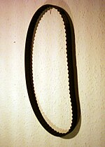
Timing belts (also known as toothed, notch, cog, or synchronous belts) are a positive transfer belt and can track relative movement. These belts have teeth that fit into a matching toothed pulley. When correctly tensioned, they have no slippage, run at constant speed, and are often used to transfer direct motion for indexing or timing purposes (hence their name). They are often used instead of chains or gears, so there is less noise and a lubrication bath is not necessary. Camshafts of automobiles, miniature timing systems, and stepper motors often utilize these belts. Timing belts need the least tension of all belts and are among the most efficient. They can bear up to 200hp (150kW) at speeds of 16,000ft/min (4,900m/min).
Timing belts with a helical offset tooth design are available. The helical offset tooth design forms a chevron pattern and causes the teeth to engage progressively. The chevron pattern design is self-aligning and does not make the noise that some timing belts make at certain speeds, and is more efficient at transferring power (up to 98%).
The advantages of timing belts include clean operation, energy efficiency, low maintenance, low noise, non slip performance, versatile load and speed capabilities.
Disadvantages include a relatively high purchase cost, the need for specially fabricated toothed pulleys, less protection from overloading, jamming, and vibration due to their continuous tension cords, the lack of clutch action (only possible with friction-drive belts), and the fixed lengths, which do not allow length adjustment (unlike link V-belts or chains).
Specialty belts
Belts normally transmit power on the tension side of the loop. However, designs for continuously variable transmissions exist that use belts that are a series of solid metal blocks, linked together as in a chain, transmitting power on the compression side of the loop.
Rolling roads
Belts used for rolling roads for wind tunnels can be capable of 250km/h (160mph).[20]
Standards for use
The open belt drive has parallel shafts rotating in the same direction, whereas the cross-belt drive also bears parallel shafts but rotate in opposite direction. The former is far more common, and the latter not appropriate for timing and standard V-belts unless there is a twist between each pulley so that the pulleys only contact the same belt surface. Nonparallel shafts can be connected if the belt's center line is aligned with the center plane of the pulley. Industrial belts are usually reinforced rubber but sometimes leather types. Non-leather, non-reinforced belts can only be used in light applications.
The pitch line is the line between the inner and outer surfaces that is neither subject to tension (like the outer surface) nor compression (like the inner). It is midway through the surfaces in film and flat belts and dependent on cross-sectional shape and size in timing and V-belts. Standard reference pitch diameter can be estimated by taking average of gear teeth tips diameter and gear teeth base diameter. The angular speed is inversely proportional to size, so the larger the one wheel, the less angular velocity, and vice versa. Actual pulley speeds tend to be 0.5–1% less than generally calculated because of belt slip and stretch. In timing belts, the inverse ratio teeth of the belt contributes to the exact measurement. The speed of the belt is:
Speed = Circumference based on pitch diameter × angular speed in rpm
International use standards
Standards include:
ISO 9563: This standard specifies requirements and test methods for endless power transmission V-belts and V-ribbed belts.
ISO 4184: This standard specifies the dimensions of classical and narrow V-belts for general use.
ISO 9981: This standard deals with the dimensions of rubber synchronous belt drives.
ISO 9982: This standard covers the dimensions of polyurethane synchronous belt drives.
DIN 22101: This standard covers the design principles for belt conveyors used in bulk material handling, including safety requirements and testing methods.
ASME B29.1: This standard specifies the dimensions, tolerances, and quality requirements for roller chain drives, which include belts and sprockets.
ANSI/RMA IP-20 is a standard developed by the American National Standards Institute (ANSI) and the Rubber Manufacturers Association (RMA) that focuses on elastomeric belts used in industrial applications. This standard covers important aspects such as dimensions and tolerances, ensuring that the belts perform reliably and efficiently in various industrial settings.
SAE J1459 is a standard developed by the Society of Automotive Engineers (SAE) that focuses on automotive V-belts and V-ribbed belts. These belts are used in various automotive applications, such as power transmission between the engine and different accessories, including the alternator, power steering pump, air conditioning compressor, and water pump. The standard specifies test procedures, performance requirements, and dimensions to ensure the belts are reliable, durable, and suitable for automotive use.
ASTM D378 is a standard developed by the American Society for Testing and Materials (ASTM), which focuses on the testing of conveyor belts used in various industries for specific applications. Conveyor belts are essential for material handling and transportation in industries such as mining, construction, agriculture, and manufacturing. ASTM D378 covers the testing methods to evaluate conveyor belts for performance characteristics, such as fire resistance and oil resistance, ensuring that they meet safety and operational requirements.[21]
Selection criteria
Belt drives are built under the following required conditions: speeds of and power transmitted between drive and driven unit; suitable distance between shafts; and appropriate operating conditions. The equation for power is
Factors of power adjustment include speed ratio; shaft distance (long or short); type of drive unit (electric motor, internal combustion engine); service environment (oily, wet, dusty); driven unit loads (jerky, shock, reversed); and pulley-belt arrangement (open, crossed, turned). These are found in engineering handbooks and manufacturer's literature. When corrected, the power is compared to rated powers of the standard belt cross-sections at particular belt speeds to find a number of arrays that perform best. Now the pulley diameters are chosen. It is generally either large diameters or large cross-section that are chosen, since, as stated earlier, larger belts transmit this same power at low belt speeds as smaller belts do at high speeds. To keep the driving part at its smallest, minimal-diameter pulleys are desired. Minimum pulley diameters are limited by the elongation of the belt's outer fibers as the belt wraps around the pulleys. Small pulleys increase this elongation, greatly reducing belt life. Minimal pulley diameters are often listed with each cross-section and speed, or listed separately by belt cross-section. After the cheapest diameters and belt section are chosen, the belt length is computed. If endless belts are used, the desired shaft spacing may need adjusting to accommodate standard-length belts. It is often more economical to use two or more juxtaposed V-belts, rather than one larger belt.
In large speed ratios or small central distances, the angle of contact between the belt and pulley may be less than 180°. If this is the case, the drive power must be further increased, according to manufacturer's tables, and the selection process repeated. This is because power capacities are based on the standard of a 180° contact angle. Smaller contact angles mean less area for the belt to obtain traction, and thus the belt carries less power.
Belt drives depend on friction to operate, but excessive friction wastes energy and rapidly wears the belt. Factors that affect belt friction include belt tension, contact angle, and the materials used to make the belt and pulleys.
Belt tension
Power transmission is a function of belt tension. However, also increasing with tension is stress (load) on the belt and bearings. The ideal belt is that of the lowest tension that does not slip in high loads. Belt tensions should also be adjusted to belt type, size, speed, and pulley diameters. Belt tension is determined by measuring the force to deflect the belt a given distance per inch (or mm) of pulley. Timing belts need only adequate tension to keep the belt in contact with the pulley.
Belt wear
Fatigue, more so than abrasion, is the culprit for most belt problems. This wear is caused by stress from rolling around the pulleys. High belt tension; excessive slippage; adverse environmental conditions; and belt overloads caused by shock, vibration, or belt slapping all contribute to belt fatigue.
Belt vibration
Vibration signatures are widely used for studying belt drive malfunctions. Some of the common malfunctions or faults include the effects of belt tension, speed, sheaveeccentricity and misalignment conditions. The effect of sheave Eccentricity on vibration signatures of the belt drive is quite significant. Although, vibration magnitude is not necessarily increased by this it will create strong amplitude modulation. When the top section of a belt is in resonance, the vibrations of the machine is increased. However, an increase in the machine vibration is not significant when only the bottom section of the belt is in resonance. The vibration spectrum has the tendency to move to higher frequencies as the tension force of the belt is increased.
Belt dressing
Belt slippage can be addressed in several ways. Belt replacement is an obvious solution, and eventually the mandatory one (because no belt lasts forever). Often, though, before the replacement option is executed, retensioning (via pulley centerline adjustment) or dressing (with any of various coatings) may be successful to extend the belt's lifespan and postpone replacement. Belt dressings are typically liquids that are poured, brushed, dripped, or sprayed onto the belt surface and allowed to spread around; they are meant to recondition the belt's driving surfaces and increase friction between the belt and the pulleys. Some belt dressings are dark and sticky, resembling tar or syrup; some are thin and clear, resembling mineral spirits. Some are sold to the public in aerosol cans at auto parts stores; others are sold in drums only to industrial users.
Specifications
To fully specify a belt, the material, length, and cross-section size and shape are required. Timing belts, in addition, require that the size of the teeth be given. The length of the belt is the sum of the central length of the system on both sides, half the circumference of both pulleys, and the square of the sum (if crossed) or the difference (if open) of the radii. Thus, when dividing by the central distance, it can be visualized as the central distance times the height that gives the same squared value of the radius difference on, of course, both sides. When adding to the length of either side, the length of the belt increases, in a similar manner to the Pythagorean theorem. One important concept to remember is that as gets closer to [further explanation needed] there is less of a distance (and therefore less addition of length) as it approaches zero.
On the other hand, in a crossed belt drive the sum rather than the difference of radii is the basis for computation for length. So the wider the small drive increases, the belt length is higher.
V-belt profiles
v-belt angle, XPZ & SPZ profile
Metric v-belt profiles (note pulley angles are reduced for small radius pulleys):
A clutch is a mechanical device that allows an output shaft to be disconnected from a rotating input shaft. The clutch's input shaft is typically attached to a motor, while the clutch's output shaft is connected to the mechanism that does the work.
Mechanical advantage is a measure of the force amplification achieved by using a tool, mechanical device or machine system. The device trades off input forces against movement to obtain a desired amplification in the output force. The model for this is the law of the lever. Machine components designed to manage forces and movement in this way are called mechanisms. An ideal mechanism transmits power without adding to or subtracting from it. This means the ideal machine does not include a power source, is frictionless, and is constructed from rigid bodies that do not deflect or wear. The performance of a real system relative to this ideal is expressed in terms of efficiency factors that take into account departures from the ideal.
A pulley is a wheel on an axle or shaft enabling a taut cable or belt passing over the wheel to move and change direction, or transfer power between itself and a shaft. A sheave or pulley wheel is a pulley using an axle supported by a frame or shell (block) to guide a cable or exert force.
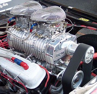
Variomatic is the continuously variable transmission (CVT) of the Dutch car manufacturer DAF, originally developed by Hub van Doorne. It is a stepless, fully-automatic transmission, consisting of a V-shaped drive-belt, and two pulleys, each of two cones, whose effective diameter can be changed so that the "V" belt runs nearer the spindle or nearer the rim, depending on the separation of the cones. These are synchronized so that the belt always remains at the same optimal tension.
Roller chain or bush roller chain is the type of chain drive most commonly used for transmission of mechanical power on many kinds of domestic, industrial and agricultural machinery, including conveyors, wire- and tube-drawing machines, printing presses, cars, motorcycles, and bicycles. It consists of a series of short cylindrical rollers held together by side links. It is driven by a toothed wheel called a sprocket. It is a simple, reliable, and efficient means of power transmission.
A continuously variable transmission (CVT) is an automated transmission that can change through a continuous range of gear ratios. This contrasts with other transmissions that provide a limited number of gear ratios in fixed steps. The flexibility of a CVT with suitable control may allow the engine to operate at a constant angular velocity while the vehicle moves at varying speeds.
A serpentine belt is a single, continuous belt used to drive multiple peripheral devices in an automotive engine, such as an alternator, power steering pump, water pump, air conditioning compressor, air pump, etc. The belt may also be guided by an idler pulley and/or a belt tensioner.
A sprocket, sprocket-wheel or chainwheel is a profiled wheel with teeth that mesh with a chain, rack or other perforated or indented material. The name 'sprocket' applies generally to any wheel upon which radial projections engage a chain passing over it. It is distinguished from a gear in that sprockets are never meshed together directly, and differs from a pulley in that sprockets have teeth and pulleys are smooth except for timing pulleys used with toothed belts.
Torsional vibration is the angular vibration of an object - commonly a shaft - along its axis of rotation. Torsional vibration is often a concern in power transmission systems using rotating shafts or couplings, where it can cause failures if not controlled. A second effect of torsional vibrations applies to passenger cars. Torsional vibrations can lead to seat vibrations or noise at certain speeds. Both reduce the comfort.
Chain drive is a way of transmitting mechanical power from one place to another. It is often used to convey power to the wheels of a vehicle, particularly bicycles and motorcycles. It is also used in a wide variety of machines besides vehicles.
A line shaft is a power-driven rotating shaft for power transmission that was used extensively from the Industrial Revolution until the early 20th century. Prior to the widespread use of electric motors small enough to be connected directly to each piece of machinery, line shafting was used to distribute power from a large central power source to machinery throughout a workshop or an industrial complex. The central power source could be a water wheel, turbine, windmill, animal power or a steam engine. Power was distributed from the shaft to the machinery by a system of belts, pulleys and gears known as millwork.
A toothed belt, timing belt, cogged belt, cog belt, or synchronous belt is a flexible belt with teeth moulded onto its inner surface. Toothed belts are usually designed to run over matching toothed pulleys or sprockets. Toothed belts are used in a wide array of mechanical devices where high power transmission is desired.
A friction drive or friction engine is a type of transmission that utilises the static friction of two smooth surfaces to transfer torque between two rotating parts.
An idler-wheel is a wheel which serves only to transmit rotation from one shaft to another, in applications where it is undesirable to connect them directly. For example, connecting a motor to the platter of a phonograph, or the crankshaft-to-camshaft gear train of an automobile.
In underground mining a hoist or winder is used to raise and lower conveyances within the mine shaft. Modern hoists are normally powered using electric motors, historically with direct current drives utilizing Ward Leonard control machines and later solid-state converters (thyristors), however modern large hoists use alternating current drives that are variable frequency controlled. There are three principal types of hoists used in mining applications:
A harmonic damper is a device fitted to the free end of the crankshaft of an internal combustion engine to counter torsional and resonance vibrations from the crankshaft. This device must be an interference fit to the crankshaft in order to operate in an effective manner. An interference fit ensures the device moves in perfect step with the crankshaft. It is essential on engines with long crankshafts and V8 engines with cross plane cranks, or V6 and straight-three engines with uneven firing order. Harmonics and torsional vibrations can greatly reduce crankshaft life, or cause instantaneous failure if the crankshaft runs at or through an amplified resonance. Dampers are designed with a specific weight (mass) and diameter, which are dependent on the damping material/method used, to reduce mechanical Q factor, or damp, crankshaft resonances.
The capstan equation or belt friction equation, also known as Euler-Eytelwein formula, relates the hold-force to the load-force if a flexible line is wound around a cylinder.
A drum motor is a geared motor drive enclosed within a steel shell providing a single component driving pulley for conveyor belts.
A rope drive is a form of belt drive, used for mechanical power transmission.
References
Wikimedia Commons has media related to Belt drives.
↑ Needham, Science and Civilization in China (1988), Volume 5, Part 9, 207–208.
1 2 Needham, Science and Civilization in China (1986), Volume 4, Part 2, 108.
↑ Needham, Science and Civilization in China (1988), Volume 5, Part 9, 160–163.
↑ By Rhys Jenkins, Newcomen Society, (1971). Links in the History of Engineering and Technology from Tudor Times, Ayer Publishing. Page 34, ISBN0-8369-2167-4.
↑ Neufeld, Dietrich, A Russian Dance of Death: Revolution and Civil War in the Ukraine, Winnipeg, Canada: Hyperion Press, 1980, p. 61.
↑ "A Modern Cement Plant Installation". Power and Transmission. XVIII (1): 17–19, 29. October 1902. Note: This journal is the house organ of the Dodge Manufacturing Company and is mostly devoted to rope-power systems.
This page is based on this Wikipedia article Text is available under the CC BY-SA 4.0 license; additional terms may apply. Images, videos and audio are available under their respective licenses.