Mechanical advantage is a measure of the force amplification achieved by using a tool, mechanical device or machine system. The device trades off input forces against movement to obtain a desired amplification in the output force. The model for this is the law of the lever. Machine components designed to manage forces and movement in this way are called mechanisms. An ideal mechanism transmits power without adding to or subtracting from it. This means the ideal machine does not include a power source, is frictionless, and is constructed from rigid bodies that do not deflect or wear. The performance of a real system relative to this ideal is expressed in terms of efficiency factors that take into account departures from the ideal.
Power is the amount of energy transferred or converted per unit time. In the International System of Units, the unit of power is the watt, equal to one joule per second. Power is a scalar quantity.

The Pelton wheel or Pelton Turbine is an impulse-type water turbine invented by American inventor Lester Allan Pelton in the 1870s. The Pelton wheel extracts energy from the impulse of moving water, as opposed to water's dead weight like the traditional overshot water wheel. Many earlier variations of impulse turbines existed, but they were less efficient than Pelton's design. Water leaving those wheels typically still had high speed, carrying away much of the dynamic energy brought to the wheels. Pelton's paddle geometry was designed so that when the rim ran at half the speed of the water jet, the water left the wheel with very little speed; thus his design extracted almost all of the water's impulse energy—which made for a very efficient turbine.

A simple machine is a mechanical device that changes the direction or magnitude of a force. In general, they can be defined as the simplest mechanisms that use mechanical advantage to multiply force. Usually the term refers to the six classical simple machines that were defined by Renaissance scientists:
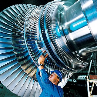
A steam turbine or steam turbine engine is a machine or heat engine that extracts thermal energy from pressurized steam and uses it to do mechanical work on a rotating output shaft. Its modern manifestation was invented by Charles Parsons in 1884. Fabrication of a modern steam turbine involves advanced metalwork to form high-grade steel alloys into precision parts using technologies that first became available in the 20th century; continued advances in durability and efficiency of steam turbines remains central to the energy economics of the 21st century.

A lever is a simple machine consisting of a beam or rigid rod pivoted at a fixed hinge, or fulcrum. A lever is a rigid body capable of rotating on a point on itself. On the basis of the locations of fulcrum, load and effort, the lever is divided into three types. It is one of the six simple machines identified by Renaissance scientists. A lever amplifies an input force to provide a greater output force, which is said to provide leverage, which is mechanical advantage gained in the system, equal to the ratio of the output force to the input force. As such, the lever is a mechanical advantage device, trading off force against movement.
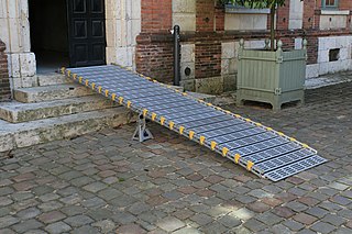
An inclined plane, also known as a ramp, is a flat supporting surface tilted at an angle from the vertical direction, with one end higher than the other, used as an aid for raising or lowering a load. The inclined plane is one of the six classical simple machines defined by Renaissance scientists. Inclined planes are used to move heavy loads over vertical obstacles. Examples vary from a ramp used to load goods into a truck, to a person walking up a pedestrian ramp, to an automobile or railroad train climbing a grade.
In electrical engineering, the maximum power transfer theorem states that, to obtain maximum external power from a power source with internal resistance, the resistance of the load must equal the resistance of the source as viewed from its output terminals. Moritz von Jacobi published the maximum power (transfer) theorem around 1840; it is also referred to as "Jacobi's law".

A block and tackle or only tackle is a system of two or more pulleys with a rope or cable threaded between them, usually used to lift heavy loads.

Carnot's theorem, also called Carnot's rule, is a principle of thermodynamics developed by Nicolas Léonard Sadi Carnot in 1824 that specifies limits on the maximum efficiency that any heat engine can obtain.
The efficiency of a system in electronics and electrical engineering is defined as useful power output divided by the total electrical power consumed, typically denoted by the Greek small letter eta.

The Rankine cycle is an idealized thermodynamic cycle describing the process by which certain heat engines, such as steam turbines or reciprocating steam engines, allow mechanical work to be extracted from a fluid as it moves between a heat source and heat sink. The Rankine cycle is named after William John Macquorn Rankine, a Scottish polymath professor at Glasgow University.

The wheel and axle is a simple machine, consisting of a wheel attached to a smaller axle so that these two parts rotate together, in which a force is transferred from one to the other. The wheel and axle can be viewed as a version of the Lever, with a drive force applied tangentially to the perimeter of the wheel, and a load force applied to the axle supported in a bearing, which serves as a fulcrum.
In electromagnetics and antenna theory, the aperture of an antenna is defined as "A surface, near or on an antenna, on which it is convenient to make assumptions regarding the field values for the purpose of computing fields at external points. The aperture is often taken as that portion of a plane surface near the antenna, perpendicular to the direction of maximum radiation, through which the major part of the radiation passes."

Rolling resistance, sometimes called rolling friction or rolling drag, is the force resisting the motion when a body rolls on a surface. It is mainly caused by non-elastic effects; that is, not all the energy needed for deformation of the wheel, roadbed, etc., is recovered when the pressure is removed. Two forms of this are hysteresis losses, and permanent (plastic) deformation of the object or the surface. Note that the slippage between the wheel and the surface also results in energy dissipation. Although some researchers have included this term in rolling resistance, some suggest that this dissipation term should be treated separately from rolling resistance because it is due to the applied torque to the wheel and the resultant slip between the wheel and ground, which is called slip loss or slip resistance. In addition, only the so-called slip resistance involves friction, therefore the name "rolling friction" is to an extent a misnomer.
In thermodynamics, the thermal efficiency is a dimensionless performance measure of a device that uses thermal energy, such as an internal combustion engine, steam turbine, steam engine, boiler, furnace, refrigerator, ACs etc.
In aerospace engineering, concerning aircraft, rocket and spacecraft design, overall propulsion system efficiency is the efficiency with which the energy contained in a vehicle's fuel is converted into kinetic energy of the vehicle, to accelerate it, or to replace losses due to aerodynamic drag or gravity. Mathematically, it is represented as , where is the cycle efficiency and is the propulsive efficiency.

The screw is a mechanism that converts rotational motion to linear motion, and a torque to a linear force. It is one of the six classical simple machines. The most common form consists of a cylindrical shaft with helical grooves or ridges called threads around the outside. The screw passes through a hole in another object or medium, with threads on the inside of the hole that mesh with the screw's threads. When the shaft of the screw is rotated relative to the stationary threads, the screw moves along its axis relative to the medium surrounding it; for example rotating a wood screw forces it into wood. In screw mechanisms, either the screw shaft can rotate through a threaded hole in a stationary object, or a threaded collar such as a nut can rotate around a stationary screw shaft. Geometrically, a screw can be viewed as a narrow inclined plane wrapped around a cylinder.

A hydraulic pump is a mechanical source of power that converts mechanical power into hydraulic energy. Hydraulic pumps are used in hydraulic drive systems and can be hydrostatic or hydrodynamic. They generate flow with enough power to overcome pressure induced by a load at the pump outlet. When a hydraulic pump operates, it creates a vacuum at the pump inlet, which forces liquid from the reservoir into the inlet line to the pump and by mechanical action delivers this liquid to the pump outlet and forces it into the hydraulic system. Hydrostatic pumps are positive displacement pumps while hydrodynamic pumps can be fixed displacement pumps, in which the displacement cannot be adjusted, or variable displacement pumps, which have a more complicated construction that allows the displacement to be adjusted. Hydrodynamic pumps are more frequent in day-to-day life. Hydrostatic pumps of various types all work on the principle of Pascal's law.

A radial turbine is a turbine in which the flow of the working fluid is radial to the shaft. The difference between axial and radial turbines consists in the way the fluid flows through the components. Whereas for an axial turbine the rotor is 'impacted' by the fluid flow, for a radial turbine, the flow is smoothly oriented perpendicular to the rotation axis, and it drives the turbine in the same way water drives a watermill. The result is less mechanical stress which enables a radial turbine to be simpler, more robust, and more efficient when compared to axial turbines. When it comes to high power ranges the radial turbine is no longer competitive and the efficiency becomes similar to that of the axial turbines.

