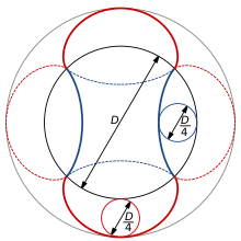
In geometry, a cycloid is the curve traced by a point on a circle as it rolls along a straight line without slipping. A cycloid is a specific form of trochoid and is an example of a roulette, a curve generated by a curve rolling on another curve.
A gear is a rotating circular machine part having cut teeth or, in the case of a cogwheel or gearwheel, inserted teeth, which mesh with another (compatible) toothed part to transmit rotational power. While doing so, they can change the torque and rotational speed being transmitted and also change the rotational axis of the power being transmitted. The teeth on the two meshing gears all have the same shape.
A rack and pinion is a type of linear actuator that comprises a circular gear engaging a linear gear. Together, they convert between rotational motion and linear motion. Rotating the pinion causes the rack to be driven in a line. Conversely, moving the rack linearly will cause the pinion to rotate. A rack-and-pinion drive can use both straight and helical gears. Though some suggest helical gears are quieter in operation, no hard evidence supports this theory. Helical racks, while being more affordable, have proven to increase side torque on the datums, increasing operating temperature leading to premature wear. Straight racks require a lower driving force and offer increased torque and speed per fraction of gear ratio which allows lower operating temperature and lessens viscal friction and energy use. The maximum force that can be transmitted in a rack-and-pinion mechanism is determined by the torque on the pinion and its size, or, conversely, by the force on the rack and the size of the pinion.
The involute gear profile is the most commonly used system for gearing today, with cycloid gearing still used for some specialties such as clocks. In an involute gear, the profiles of the teeth are involutes of a circle. The involute of a circle is the spiraling curve traced by the end of an imaginary taut string unwinding itself from that stationary circle called the base circle, or (equivalently) a triangle wave projected on the circumference of a circle.

Hobbing is a machining process for gear cutting, cutting splines, and cutting sprockets using a hobbing machine, a specialized milling machine. The teeth or splines of the gear are progressively cut into the material by a series of cuts made by a cutting tool called a hob.

A ratchet is a mechanical device that allows continuous linear or rotary motion in only one direction while preventing motion in the opposite direction. Ratchets are widely used in machinery and tools. The word ratchet is also used informally to refer to a ratcheting socket wrench.
An escapement is a mechanical linkage in mechanical watches and clocks that gives impulses to the timekeeping element and periodically releases the gear train to move forward, advancing the clock's hands. The impulse action transfers energy to the clock's timekeeping element to replace the energy lost to friction during its cycle and keep the timekeeper oscillating. The escapement is driven by force from a coiled spring or a suspended weight, transmitted through the timepiece's gear train. Each swing of the pendulum or balance wheel releases a tooth of the escapement's escape wheel, allowing the clock's gear train to advance or "escape" by a fixed amount. This regular periodic advancement moves the clock's hands forward at a steady rate. At the same time, the tooth gives the timekeeping element a push, before another tooth catches on the escapement's pallet, returning the escapement to its "locked" state. The sudden stopping of the escapement's tooth is what generates the characteristic "ticking" sound heard in operating mechanical clocks and watches.

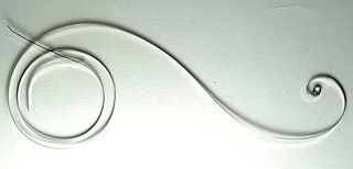
In mathematics, an involute is a particular type of curve that is dependent on another shape or curve. An involute of a curve is the locus of a point on a piece of taut string as the string is either unwrapped from or wrapped around the curve.

In horology, a movement, also known as a caliber or calibre, is the mechanism of a watch or timepiece, as opposed to the case, which encloses and protects the movement, and the face, which displays the time. The term originated with mechanical timepieces, whose clockwork movements are made of many moving parts. The movement of a digital watch is more commonly known as a module.
A mainspring is a spiral torsion spring of metal ribbon—commonly spring steel—used as a power source in mechanical watches, some clocks, and other clockwork mechanisms. Winding the timepiece, by turning a knob or key, stores energy in the mainspring by twisting the spiral tighter. The force of the mainspring then turns the clock's wheels as it unwinds, until the next winding is needed. The adjectives wind-up and spring-powered refer to mechanisms powered by mainsprings, which also include kitchen timers, metronomes, music boxes, wind-up toys and clockwork radios.
In horology, the anchor escapement is a type of escapement used in pendulum clocks. The escapement is a mechanism in a mechanical clock that maintains the swing of the pendulum by giving it a small push each swing, and allows the clock's wheels to advance a fixed amount with each swing, moving the clock's hands forward. The anchor escapement was so named because one of its principal parts is shaped vaguely like a ship's anchor.

Chain drive is a way of transmitting mechanical power from one place to another. It is often used to convey power to the wheels of a vehicle, particularly bicycles and motorcycles. It is also used in a wide variety of machines besides vehicles.

A gear train or gear set is a machine element of a mechanical system formed by mounting two or more gears on a frame such that the teeth of the gears engage.
A cycloidal drive or cycloidal speed reducer is a mechanism for reducing the speed of an input shaft by a certain ratio. Cycloidal speed reducers are capable of relatively high ratios in compact sizes with very low backlash.

Bevel gears are gears where the axes of the two shafts intersect and the tooth-bearing faces of the gears themselves are conically shaped. Bevel gears are most often mounted on shafts that are 90 degrees apart, but can be designed to work at other angles as well. The pitch surface of bevel gears is a cone, known as a pitch cone. Bevel gears change the axis of rotation of rotational power delivery and are widely used in mechanical settings.

Spur gears or straight-cut gears are the simplest type of gear. They consist of a cylinder or disk with teeth projecting radially. Viewing the gear at 90 degrees from the shaft length the tooth faces are straight and aligned parallel to the axis of rotation. Looking down the length of the shaft, a tooth's cross section is usually not triangular. Instead of being straight the sides of the cross section have a curved form to achieve a constant drive ratio. Spur gears mesh together correctly only if fitted to parallel shafts. No axial thrust is created by the tooth loads. Spur gears are excellent at moderate speeds but tend to be noisy at high speeds.

A mechanical watch is a watch that uses a clockwork mechanism to measure the passage of time, as opposed to quartz watches which function using the vibration modes of a piezoelectric quartz tuning fork, or radio watches, which are quartz watches synchronized to an atomic clock via radio waves. A mechanical watch is driven by a mainspring which must be wound either periodically by hand or via a self-winding mechanism. Its force is transmitted through a series of gears to power the balance wheel, a weighted wheel which oscillates back and forth at a constant rate. A device called an escapement releases the watch's wheels to move forward a small amount with each swing of the balance wheel, moving the watch's hands forward at a constant rate. The escapement is what makes the 'ticking' sound which is heard in an operating mechanical watch. Mechanical watches evolved in Europe in the 17th century from spring powered clocks, which appeared in the 15th century.

The profile angle of a gear is the angle at a specified pitch point between a line tangent to a tooth surface and the line normal to the pitch surface. This definition is applicable to every type of gear for which a pitch surface can be defined. The profile angle gives the direction of the tangent to a tooth profile.
In horology, a wheel train is the gear train of a mechanical watch or clock. Although the term is used for other types of gear trains, the long history of mechanical timepieces has created a traditional terminology for their gear trains which is not used in other applications of gears.