The addendum is the height by which a tooth of a gear projects beyond (outside for external, or inside for internal) the standard pitch circle or pitch line; also, the radial distance between the pitch diameter and the outside diameter.[1]
Addendum angle
Addendum angle in a bevel gear, is the angle between face cone and pitch cone.[1]
Addendum circle
Internal gear diametersRoot circle
The addendum circle coincides with the tops of the teeth of a gear and is concentric with the standard (reference) pitch circle and radially distant from it by the amount of the addendum. For external gears, the addendum circle lies on the outside cylinder while on internal gears the addendum circle lies on the internal cylinder.[1]
Apex to back, in a bevel gear or hypoid gear, is the distance in the direction of the axis from the apex of the pitch cone to a locating surface at the back of the blank.[1]
Back angle
The back angle of a bevel gear is the angle between an element of the back cone and a plane of rotation, and usually is equal to the pitch angle.[1]
Back cone
Principal dimensions
The back cone of a bevel or hypoid gear is an imaginary cone tangent to the outer ends of the teeth, with its elements perpendicular to those of the pitch cone. The surface of the gear blank at the outer ends of the teeth is customarily formed to such a back cone.[1]
Back cone distance
Back cone distance in a bevel gear is the distance along an element of the back cone from its apex to the pitch cone.[1]
In mechanical engineering, backlash is the striking back of connected wheels in a piece of mechanism when pressure is applied. Another source defines it as the maximum distance through which one part of something can be moved without moving a connected part. It is also called lash or play. In the context of gears, backlash is clearance between mating components, or the amount of lost motion due to clearance or slackness when movement is reversed and contact is re-established. In a pair of gears, backlash is the amount of clearance between mated gear teeth.
Backlash is unavoidable for nearly all reversing mechanical couplings, although its effects can be negated. Depending on the application it may or may not be desirable. Reasons for requiring backlash include allowing for lubrication and thermal expansion, and to prevent jamming. Backlash may also result from manufacturing errors and deflection under load.
The term bull gear is used to refer to the larger of two spur gears that are in engagement in any machine. The smaller gear is usually referred to as a pinion.[2]
Center distance
Center distance
Center distance (operating) is the shortest distance between non-intersecting axes. It is measured along the mutual perpendicular to the axes, called the line of centers. It applies to spur gears, parallel axis or crossed axis helical gears, and worm gearing.[1]
Central plane
Central plane
The central plane of a worm gear is perpendicular to the gear axis and contains the common perpendicular of the gear and worm axes. In the usual case with axes at right angles, it contains the worm axis.[1]
Circular Pitch
The Circular Pitch defines the width of one tooth and one gap measured on an arc on the pitch circle; in other words, this is the distance on the pitch circle from a point on one tooth to the corresponding point on the adjacent tooth. This is equal to π divided by the Diametral Pitch.
The composite action test (double flank) is a method of inspection in which the work gear is rolled in tight double flank contact with a master gear or a specified gear, in order to determine (radial) composite variations (deviations). The composite action test must be made on a variable center distance composite action test device.[1] and this is composite action test for double flank
Cone distance
Cone distance
Cone distance in a bevel gear is the general term for the distance along an element of the pitch cone from the apex to any given position in the teeth.[1]
Outer cone distance in bevel gears is the distance from the apex of the pitch cone to the outer ends of the teeth. When not otherwise specified, the short term cone distance is understood to be outer cone distance.
Mean cone distance in bevel gears is the distance from the apex of the pitch cone to the middle of the face width.
Inner cone distance in bevel gears is the distance from the apex of the pitch cone to the inner ends of the teeth.
Conjugate gears
Conjugate gears transmit uniform rotary motion from one shaft to another by means of gear teeth. The normals to the profiles of these teeth, at all points of contact, must pass through a fixed point in the common centerline of the two shafts.[1] Usually conjugate gear tooth is made to suit the profile of other gear which is not made based on standard practice.
Crossed helical gear
A crossed helical gear is a gear that operate on non-intersecting, non-parallel axes.
The term crossed helical gears has superseded the term spiral gears. There is theoretically point contact between the teeth at any instant. They have teeth of the same or different helix angles, of the same or opposite hand. A combination of spur and helical or other types can operate on crossed axes.[1]
Crossing point
The crossing point is the point of intersection of bevel gear axes; also the apparent point of intersection of the axes in hypoid gears, crossed helical gears, worm gears, and offset face gears, when projected to a plane parallel to both axes.[1]
Crown circle
The crown circle in a bevel or hypoid gear is the circle of intersection of the back cone and face cone.[1]
Crowned teeth
Crowned gear
Crowned teeth have surfaces modified in the lengthwise direction to produce localized contact or to prevent contact at their ends.[1]
Diametral Pitch
The Diametral Pitch (DP) is the number of teeth per inch of diameter of the pitch circle. The units of DP are inverse inches (1/in).[3]
DP = Diametral Pitch
PD = Pitch Circle Diameter in inches
CP = Circular Pitch in inches
n = Number of Teeth
DP = n / PD
The Diametral Pitch (DP) is equal to π divided by the Circular Pitch (CP).
DP = 3.1416 / CP
Dedendum angle
Dedendum angle in a bevel gear, is the angle between elements of the root cone and pitch cone.[1]
Equivalent pitch radius
Back cone equivalent
Equivalent pitch radius is the radius of the pitch circle in a cross section of gear teeth in any plane other than a plane of rotation. It is properly the radius of curvature of the pitch surface in the given cross section. Examples of such sections are the transverse section of bevel gear teeth and the normal section of helical teeth.
Face (tip) angle
Face (tip) angle in a bevel or hypoid gear, is the angle between an element of the face cone and its axis.[1]
Face cone
The face cone, also known as the tip cone is the imaginary surface that coincides with the tops of the teeth of a bevel or hypoid gear.[1]
A face gear set typically consists of a disk-shaped gear, grooved on at least one face, in combination with a spur, helical, or conical pinion. A face gear has a planar pitch surface and a planar root surface, both of which are perpendicular to the axis of rotation.[1] It can also be referred to as a face wheel, crown gear, crown wheel, contrate gear or contrate wheel.
Face width
Face width
The face width of a gear is the length of teeth in an axial plane. For double helical, it does not include the gap.[1]
Total face width is the actual dimension of a gear blank including the portion that exceeds the effective face width, or as in double helical gears where the total face width includes any distance or gap separating right hand and left hand helices.
For a cylindrical gear, effective face width is the portion that contacts the mating teeth. One member of a pair of gears may engage only a portion of its mate.
For a bevel gear, different definitions for effective face width are applicable.
Form diameter
Form diameter
Form diameter is the diameter of a circle at which the trochoid (fillet curve) produced by the tooling intersects, or joins, the involute or specified profile. Although these terms are not preferred, it is also known as the true involute form diameter (TIF), start of involute diameter (SOI), or when undercut exists, as the undercut diameter. This diameter cannot be less than the base circle diameter.[1]
Front angle
The front angle, in a bevel gear, denotes the angle between an element of the front cone and a plane of rotation, and usually equals the pitch angle.[1]
Front cone
The front cone of a hypoid or bevel gear is an imaginary cone tangent to the inner ends of the teeth, with its elements perpendicular to those of the pitch cone. The surface of the gear blank at the inner ends of the teeth is customarily formed to such a front cone, but sometimes may be a plane on a pinion or a cylinder in a nearly flat gear.[1]
Gear center
A gear center is the center of the pitch circle.[1]
Gear range
The gear range is difference between the highest and lowest gear ratios and may be expressed as a percentage (e.g., 500%) or as a ratio (e.g., 5:1).
Heel
Heel and toe
The heel of a tooth on a bevel gear or pinion is the portion of the tooth surface near its outer end.
The toe of a tooth on a bevel gear or pinion is the portion of the tooth surface near its inner end.[1]
Helical rack
A helical rack has a planar pitch surface and teeth that are oblique to the direction of motion.[1]
Helix angle
Helix angle is the angle between the helical tooth face and an equivalent spur tooth face. For the same lead, the helix angle is greater for larger gear diameters. It is understood to be measured at the standard pitch diameter unless otherwise specified.
The displacement of any tooth flank from its theoretical position, relative to a datum tooth flank.
Distinction is made as to the direction and algebraic sign of this reading. A condition wherein the actual tooth flank position was nearer to the datum tooth flank, in the specified measuring path direction (clockwise or counterclockwise), than the theoretical position would be considered a minus (-) deviation. A condition wherein the actual tooth flank position was farther from the datum tooth flank, in the specified measuring path direction, than the theoretical position would be considered a plus (+) deviation.
The direction of tolerancing for index deviation along the arc of the tolerance diameter circle within the transverse plane.[1]
Inside cylinder
Diameters, Internal Gear
The inside cylinder is the surface that coincides with the tops of the teeth of an internal cylindrical gear.[1]
Inside diameter
Internal gear diameters
Inside diameter is the diameter of the addendum circle of an internal gear, this is also known as minor diameter.[1]
Expressed as θ, the involute polar angle is the angle between a radius vector to a point, P, on an involute curve and a radial line to the intersection, A, of the curve with the base circle.[1]
Involute roll angle
Involute roll angle
Expressed as ε, the involute roll angle is the angle whose arc on the base circle of radius unity equals the tangent of the pressure angle at a selected point on the involute.[1]
Involute teeth
Involute teeth
Involute teeth of spur gears, helical gears, and worms are those in which the profile in a transverse plane (exclusive of the fillet curve) is the involute of a circle.[1]
The bottom land is the surface at the bottom of a gear tooth space adjoining the fillet.[1]
Top land
Top land is the (sometimes flat) surface of the top of a gear tooth.[1]
Lead
Lead is the axial advance of a helix gear tooth during one complete turn (360°), that is, the Lead is the axial travel (length along the axle) for one single complete helical revolution about the pitch diameter of the gear.
Lead angle is 90° to the helix angle between the helical tooth face and an equivalent spur tooth face. For the same lead, the lead angle is larger for smaller gear diameters. It is understood to be measured at the standard pitch diameter unless otherwise specified.
A spur gear tooth has a lead angle of 90°, and a helix angle of 0°.
The line of centers connects the centers of the pitch circles of two engaging gears; it is also the common perpendicular of the axes in crossed helical gears and worm gears. When one of the gears is a rack, the line of centers is perpendicular to its pitch line.[1]
Module
The module is the measure of gear tooth size which is normally used for metric system gears. It is similar to the Diametral Pitch (DP), which is commonly used for UK system (inch measure) gears but they differ in the units used and in that they bear a reciprocal relationship. Module is the pitch circle diameter divided by the number of teeth. Module may also be applied to UK system gears, using inch units, but this usage is not in common use. Module is commonly expressed in units of millimeters (mm).
MM = Metric Module
PD = Pitch Circle Diameter in mm
n = Number of Teeth
MM = PD / n
UK system (inch measure) gears are more commonly specified with the Diametral Pitch (DP) which is the number of teeth per inch of diameter of the pitch circle. The units of DP are inverse inches (1/in).
DP = Diametral Pitch
PD = Pitch Circle Diameter in inches
n = Number of Teeth
DP = n / PD
When converting between module and DP there is an inverse relationship and normally a conversion between the two units of measure (inches and millimeter). Taking both of these into consideration the formulae for conversion are:
Mounting distance, for assembling bevel gears or hypoid gears, is the distance from the crossing point of the axes to a locating surface of a gear, which may be at either back or front.[1]
Normal module
Normal module is the value of the module in a normal plane of a helical gear or worm.[1]
Normal plane
Planes at a pitch point on a helical tooth
A normal plane is normal to a tooth surface at a pitch point, and perpendicular to the pitch plane. In a helical rack, a normal plane is normal to all the teeth it intersects. In a helical gear, however, a plane can be normal to only one tooth at a point lying in the plane surface. At such a point, the normal plane contains the line normal to the tooth surface.
Important positions of a normal plane in tooth measurement and tool design of helical teeth and worm threads are:
the plane normal to the pitch helix at side of tooth;
the plane normal to the pitch helix at center of tooth;
the plane normal to the pitch helix at center of space between two teeth
In a spiral bevel gear, one of the positions of a normal plane is at a mean point and the plane is normal to the tooth trace.[1]
Offset
Offset
Offset is the perpendicular distance between the axes of hypoid gears or offset face gears.[1]
In the adjacent diagram, (a) and (b) are referred to as having an offset below center, while those in (c) and (d) have an offset above center. In determining the direction of offset, it is customary to look at the gear with the pinion at the right. For below center offset the pinion has a left hand spiral, and for above center offset the pinion has a right hand spiral.
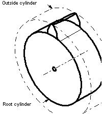
Outside cylinder
Cylindrical surfaces
The outside (tip or addendum) cylinder is the surface that coincides with the tops of the teeth of an external cylindrical gear.[1]
Outside diameter
Wormgear diameters
The outside diameter of a gear is the diameter of the addendum (tip) circle. In a bevel gear it is the diameter of the crown circle. In a throated worm gear it is the maximum diameter of the blank. The term applies to external gears, this is can also be known from major diameter.[1]
A pinion is a round gear and usually refers to the smaller of two meshed gears.
Pitch angle
Angle relationships
Angles
Pitch Angle examples
Pitch angle in bevel gears is the angle between an element of a pitch cone and its axis. In external and internal bevel gears, the pitch angles are respectively less than and greater than 90 degrees.[1]
Pitch circle
A pitch circle (operating) is the curve of intersection of a pitch surface of revolution and a plane of rotation. It is the imaginary circle that rolls without slipping with a pitch circle of a mating gear.[1] These are the outlines of mating gears. Many important measurements are taken on and from this circle.[1]
Pitch cone
Pitch cones
A pitch cone is the imaginary cone in a bevel gear that rolls without slipping on a pitch surface of another gear.[1]
Pitch helix
Tooth helix
The pitch helix is the intersection of the tooth surface and the pitch cylinder of a helical gear or cylindrical worm.[1]
Base helix
The base helix of a helical, involute gear or involute worm lies on its base cylinder.
Base helix angle
Base helix angle is the helix angle on the base cylinder of involute helical teeth or threads.
Base lead angle
Base lead angle is the lead angle on the base cylinder. It is the complement of the base helix angle.
Outside helix
The outside (tip or addendum) helix is the intersection of the tooth surface and the outside cylinder of a helical gear or cylindrical worm.
Outside helix angle
Normal helix
Outside helix angle is the helix angle on the outside cylinder.
Outside lead angle
Outside lead angle is the lead angle on the outside cylinder. It is the complement of the outside helix angle.
Normal helix
A normal helix is a helix on the pitch cylinder, normal to the pitch helix.
Pitch line
The pitch line corresponds, in the cross section of a rack, to the pitch circle (operating) in the cross section of a gear.[1]
Pitch point
The pitch point is the point of tangency of two pitch circles (or of a pitch circle and pitch line) and is on the line of centers.[1]
Pitch surfaces
Pitch surfaces
Pitch surfaces are the imaginary planes, cylinders, or cones that roll together without slipping. For a constant velocity ratio, the pitch cylinders and pitch cones are circular.[1]
Pitch cones
Planes
Pitch plane
Pitch planes
The pitch plane of a pair of gears is the plane perpendicular to the axial plane and tangent to the pitch surfaces. A pitch plane in an individual gear may be any plane tangent to its pitch surface.
The pitch plane of a rack or in a crown gear is the imaginary planar surface that rolls without slipping with a pitch cylinder or pitch cone of another gear. The pitch plane of a rack or crown gear is also the pitch surface.[1]
Transverse plane
The transverse plane is perpendicular to the axial plane and to the pitch plane. In gears with parallel axes, the transverse and the plane of rotation coincide.[1]
Principal directions
Principal directions
Principal directions are directions in the pitch plane, and correspond to the principal cross sections of a tooth.
The axial direction is a direction parallel to an axis.
The transverse direction is a direction within a transverse plane.
The normal direction is a direction within a normal plane.[1]
Profile radius of curvature is the radius of curvature of a tooth profile, usually at the pitch point or a point of contact. It varies continuously along the involute profile.[1]
Tooth-to-tooth radial composite deviation (double flank) is the greatest change in center distance while the gear being tested is rotated through any angle of 360 degree/z during double flank composite action test.
Tooth-to-tooth radial composite tolerance (double flank) is the permissible amount of tooth-to-tooth radial composite deviation.
Total radial composite deviation (double flank) is the total change in center distance while the gear being tested is rotated one complete revolution during a double flank composite action test.
Total radial composite tolerance (double flank) is the permissible amount of total radial composite deviation.[1]
Root angle
Root angle in a bevel or hypoid gear, is the angle between an element of the root cone and its axis.[1]
Root circle
External gear
Internal gear
Root Circles for internal & external gears
The root circle coincides with the bottoms of the tooth spaces.[1]
Root cone
Principal dimensions
The root cone is the imaginary surface that coincides with the bottoms of the tooth spaces in a bevel or hypoid gear.[1]
Root cylinder
The root cylinder is the imaginary surface that coincides with the bottoms of the tooth spaces in a cylindrical gear.[1]
Shaft angle
Shaft angle
A shaft angle is the angle between the axes of two non-parallel gear shafts. In a pair of crossed helical gears, the shaft angle lies between the oppositely rotating portions of two shafts. This applies also in the case of worm gearing. In bevel gears, the shaft angle is the sum of the two pitch angles. In hypoid gears, the shaft angle is given when starting a design, and it does not have a fixed relation to the pitch angles and spiral angles.[1]
A spur gear has a cylindrical pitch surface and teeth that are parallel to the axis.[1]
Spur rack
A spur rack has a planar pitch surface and straight teeth that are at right angles to the direction of motion.[1]
Standard pitch circle
The standard pitch circle is the circle which intersects the involute at the point where the pressure angle is equal to the profile angle of the basic rack.[1]
Standard pitch diameter
The standard reference pitch diameter is the diameter of the standard pitch circle. In spur and helical gears, unless otherwise specified, the standard pitch diameter is related to the number of teeth and the standard transverse pitch. Standard reference pitch diameter can be estimated by taking average of gear teeth tips diameter and gear teeth base diameter.[1]
The pitch diameter is useful in determining the spacing between gear centers because proper spacing of gears implies tangent pitch circles. The pitch diameters of two gears may be used to calculate the gear ratio in the same way the number of teeth is used.
Where is the total number of teeth, is the circular pitch, is the diametrical pitch, and is the helix angle for helical gears.
Standard reference pitch diameter
The standard reference pitch diameter is the diameter of the standard pitch circle. In spur and helical gears, unless otherwise specified, the standard pitch diameter is related to the number of teeth and the standard transverse pitch. It is obtained as:[1]
Test radius
The test radius (Rr) is a number used as an arithmetic convention established to simplify the determination of the proper test distance between a master and a work gear for a composite action test. It is used as a measure of the effective size of a gear. The test radius of the master, plus the test radius of the work gear is the set up center distance on a composite action test device. Test radius is not the same as the operating pitch radii of two tightly meshing gears unless both are perfect and to basic or standard tooth thickness.[1]
Throat diameter
Worm gear diameters
The throat diameter is the diameter of the addendum circle at the central plane of a worm gear or of a double-enveloping worm gear.[1]
Throat form radius
Throat form radius is the radius of the throat of an enveloping worm gear or of a double-enveloping worm, in an axial plane.[1]
Tip radius
Tip radius
Tip radius is the radius of the circular arc used to join a side-cutting edge and an end-cutting edge in gear cutting tools. Edge radius is an alternate term.[1]
Tip relief
Tip relief
Tip relief is a modification of a tooth profile whereby a small amount of material is removed near the tip of the gear tooth.[1]
Tooth surface
Profile of a spur gearNotation and numbering for an external gearNotation and numbering for an internal gear
The tooth surface (flank) forms the side of a gear tooth.[1]
It is convenient to choose one face of the gear as the reference face and to mark it with the letter “I”. The other non-reference face might be termed face “II”.
For an observer looking at the reference face, so that the tooth is seen with its tip uppermost, the right flank is on the right and the left flank is on the left. Right and left flanks are denoted by the letters “R” and “L” respectively.
1 2 3 Machinery's Handbook Twenty-Fifth Edition, by Erik Oberg, Franklin D. Jones, Holbrook L. Horton, and Henry H Ryffle, 1996, Industrial Press Inc.
This page is based on this Wikipedia article Text is available under the CC BY-SA 4.0 license; additional terms may apply. Images, videos and audio are available under their respective licenses.