A gear is a rotating circular machine part having cut teeth or, in the case of a cogwheel or gearwheel, inserted teeth, which mesh with another (compatible) toothed part to transmit (convert) torque and speed. The basic principle behind the operation of gears is analogous to the basic principle of levers. A gear may also be known informally as a cog. Geared devices can change the speed, torque, and direction of a power source. Gears of different sizes produce a change in torque, creating a mechanical advantage, through their gear ratio, and thus may be considered a simple machine. The rotational speeds, and the torques, of two meshing gears differ in proportion to their diameters. The teeth on the two meshing gears all have the same shape.
A rack and pinion is a type of linear actuator that comprises a circular gear engaging a linear gear, which operate to translate rotational motion into linear motion. Driving the pinion into rotation causes the rack to be driven linearly. Driving the rack linearly will cause the pinion to be driven into a rotation. A rack and pinion drive can use both straight and helical gears. Though some suggest Helical gears are noted for “quieter” operation, there is no science to support this theory. Helical racks while being more affordable, have proven to increase side torque on the datums, increasing operating temperature leading to premature wear. Straight racks require a lower driving force and offer increased torque and speed per percentage of gear ratio which allows lower operating temperature and lessens viscal friction and energy use. The maximum force that can be transmitted in a rack and pinion mechanism is determined by the tooth pitch and the size of the pinion as well as the gear ratio..
The involute gear profile is the most commonly used system for gearing today, with cycloid gearing still used for some specialties such as clocks. In an involute gear, the profiles of the teeth are involutes of a circle. The involute of a circle is the spiraling curve traced by the end of an imaginary taut string unwinding itself from that stationary circle called the base circle, or (equivalently) a triangle wave projected on the circumference of a circle.

Hobbing is a machining process for gear cutting, cutting splines, and cutting sprockets on a hobbing machine, which is a special type of milling machine. The teeth or splines of the gear are progressively cut into the material by a series of cuts made by a cutting tool called a hob. Compared to other gear forming processes it is relatively inexpensive but still quite accurate, thus it is used for a broad range of parts and quantities.
Broaching is a machining process that uses a toothed tool, called a broach, to remove material. There are two main types of broaching: linear and rotary. In linear broaching, which is the more common process, the broach is run linearly against a surface of the workpiece to produce the cut. Linear broaches are used in a broaching machine, which is also sometimes shortened to broach. In rotary broaching, the broach is rotated and pressed into the workpiece to cut an axisymmetric shape. A rotary broach is used in a lathe or screw machine. In both processes the cut is performed in one pass of the broach, which makes it very efficient.
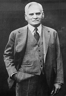
Edwin R. Fellows was an American inventor and entrepreneur from Torrington, Connecticut who designed and built a new type of gear shaper in 1896 and, with the mentoring of James Hartness, left the Jones & Lamson Machine Company to co-found the Fellows Gear Shaper Company in Springfield, Vermont, which became one of the leading firms in the gear-cutting segment of the machine tool industry. Fellows' machines made a vital contribution to the mass production of effective and reliable gear transmissions for the nascent automotive industry. By the conclusion of World War II, Fellows Gear Shaper Company machines were in defense contractor plants, manufacturing geared components for aircraft engines, tanks, instruments, cameras, fuses and other war-time materiel.
Milling cutters are cutting tools typically used in milling machines or machining centres to perform milling operations. They remove material by their movement within the machine or directly from the cutter's shape.

A worm drive is a gear arrangement in which a worm meshes with a worm wheel. The two elements are also called the worm screw and worm gear. The terminology is often confused by imprecise use of the term worm gear to refer to the worm, the worm wheel, or the worm drive as a unit.

Bevel gears are gears where the axes of the two shafts intersect and the tooth-bearing faces of the gears themselves are conically shaped. Bevel gears are most often mounted on shafts that are 90 degrees apart, but can be designed to work at other angles as well. The pitch surface of bevel gears is a cone.
Gear cutting is any machining process for creating a gear. The most common gear-cutting processes include hobbing, broaching, milling, and grinding. Such cutting operations may occur either after or instead of forming processes such as forging, extruding, investment casting, or sand casting.

Spur gears or straight-cut gears are the simplest type of gear. They consist of a cylinder or disk with teeth projecting radially. Viewing the gear at 90 degrees from the shaft length the tooth faces are straight and aligned parallel to the axis of rotation. Looking down the length of the shaft, a tooth's cross section is usually not triangular. Instead of being straight the sides of the cross section have a curved form to achieve a constant drive ratio. Spur gears gears mesh together correctly only if fitted to parallel shafts. No axial thrust is created by the tooth loads. Spur gears are excellent at moderate speeds but tend to be noisy at high speeds.
Gear manufacturing refers to the making of gears. Gears can be manufactured by a variety of processes, including casting, forging, extrusion, powder metallurgy, and blanking. As a general rule, however, machining is applied to achieve the final dimensions, shape and surface finish in the gear. The initial operations that produce a semifinishing part ready for gear machining as referred to as blanking operations; the starting product in gear machining is called a gear blank.

In mechanical engineering, backlash, sometimes called lash, play, or slop, is a clearance or lost motion in a mechanism caused by gaps between the parts. It can be defined as "the maximum distance or angle through which any part of a mechanical system may be moved in one direction without applying appreciable force or motion to the next part in mechanical sequence."p. 1-8 An example, in the context of gears and gear trains, is the amount of clearance between mated gear teeth. It can be seen when the direction of movement is reversed and the slack or lost motion is taken up before the reversal of motion is complete. It can be heard from the railway couplings when a train reverses direction. Another example is in a valve train with mechanical tappets, where a certain range of lash is necessary for the valves to work properly.

Pressure angle in relation to gear teeth, also known as the angle of obliquity, is the angle between the tooth face and the gear wheel tangent. It is more precisely the angle at a pitch point between the line of pressure and the plane tangent to the pitch surface. The pressure angle gives the direction normal to the tooth profile. The pressure angle is equal to the profile angle at the standard pitch circle and can be termed the "standard" pressure angle at that point. Standard values are 14.5 and 20 degrees. Earlier gears with pressure angle 14.5 were commonly used because the cosine is larger for a smaller angle, providing more power transmission and less pressure on the bearing; however, teeth with smaller pressure angles are weaker. To run gears together properly their pressure angles must be matched.
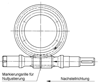
A duplex worm or dual lead worm is a worm gear set where the two flanks are manufactured with slightly different modules and/or diameter quotients. As a result of this, different lead angles on both tooth profiles are obtained, so that the tooth thickness is continuously increasing all over the worm length, while the gap between two threads is decreasing. This allows control of backlash.
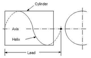
Lead is the axial advance of a helix or screw during one complete turn (360°) The lead for a screw thread is the axial travel for a single revolution.

A spiral bevel gear is a bevel gear with helical teeth. The main application of this is in a vehicle differential, where the direction of drive from the drive shaft must be turned 90 degrees to drive the wheels. The helical design produces less vibration and noise than conventional straight-cut or spur-cut gear with straight teeth.

A herringbone gear, a specific type of double helical gear, is a special type of gear that is a side-to-side combination of two helical gears of opposite hands. From the top, each helical groove of this gear looks like the letter V, and many together form a herringbone pattern. Unlike helical gears, herringbone gears do not produce an additional axial load.
Gashing is a machining process used to rough out coarse pitched gears and sprockets. It is commonly used on worm wheels before hobbing, but also used on internal and external spur gears, bevel gears, helical gears, and gear racks. The process is performed on gashers or universal milling machines, especially in the case of worm wheels. After gashing the gear or sprocket is finished via hobbing, shaping, or shaving.


